Wireless power feeder, wireless power transmission system, and table and table lamp using the same

a technology of wireless transmission system and feeder, which is applied in the direction of dc-ac conversion without reversal, inductance, transportation and packaging, etc., can solve the problem of not being able to feed big electric power, and achieve the effect of easy control of transmission power

Active Publication Date: 2013-11-12
TDK CORPARATION
View PDF14 Cites 21 Cited by
  • Summary
  • Abstract
  • Description
  • Claims
  • Application Information

AI Technical Summary

Benefits of technology

[0016]A main object of the present invention is to effectively control transmission power in wireless power feeding of a magnetic field resonance type.
[0019]When the drive frequency of the power transmission control circuit and resonance frequency are made coincide with each other, the power transmission efficiency in the entire system can be enhanced. The current and voltage phases of the AC power are compared to detect the phase difference between them, and the drive frequency is adjusted so as to reduce the detected phase difference, whereby it is possible to allow the drive frequency to track the resonance frequency. As a result, it makes easier for the power transmission efficiency to be kept at a high level.
[0020]Further, when the detection value of the voltage or current phase is intentionally changed, the power transmission control circuit determines that the phase difference occurs even though the resonance state is actually maintained. The power transmission control circuit automatically adjusts the drive frequency based on the phase difference. Accordingly, the drive frequency and resonance frequency becomes non-coincident with each other to reduce the power transmission efficiency. As a result, it is possible to realize wireless power feeding capable of easily achieving manual control of the power transmission efficiency while automatically pursuing the maximum power transmission efficiency.
[0026]A table lamp with wireless power receiving function according to the present invention receives, using a receiving coil, AC power transmitted from the abovementioned table by wireless. The table lamp includes: a receiving coil circuit that includes the receiving coil and a capacitor and resonates at the resonance frequency of the feeding coil; and a loading circuit that includes a loading coil that is magnetically coupled to the receiving coil to receive the AC power from the receiving coil and a lamp that receives power from the loading coil. When the table lamp is placed on the table, the receiving coil receives the AC power fed from the feeding coil provided in the table to turn on the lamp. This configuration eliminated the need of providing a power cord, thus being advantageous in terms of appearance and safety.
[0028]According to the present invention, it is possible to easily perform control of transmission power in wireless power feeding of a magnetic field resonance type.

Problems solved by technology

The type (B) utilizing radio wave is available in a long range; however, it cannot feed big electric power.

Method used


Image

  • Wireless power feeder, wireless power transmission system, and table and table lamp using the same
  • Wireless power feeder, wireless power transmission system, and table and table lamp using the same
  • Wireless power feeder, wireless power transmission system, and table and table lamp using the same

Examples


Embodiment Construction

[0047]A preferred embodiment of the present invention will be described below with reference to the accompanying drawings.

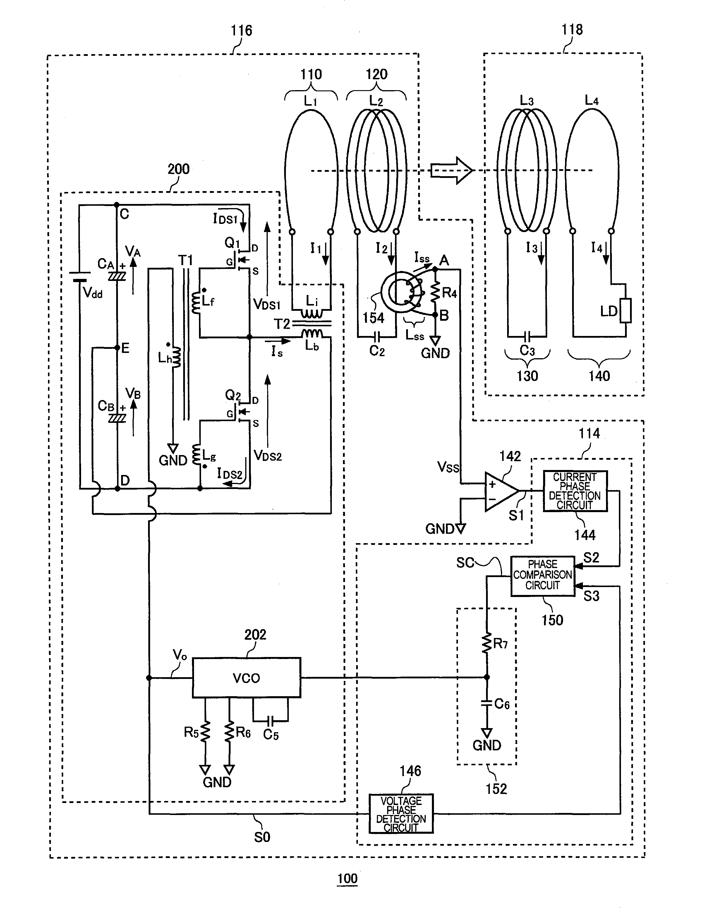
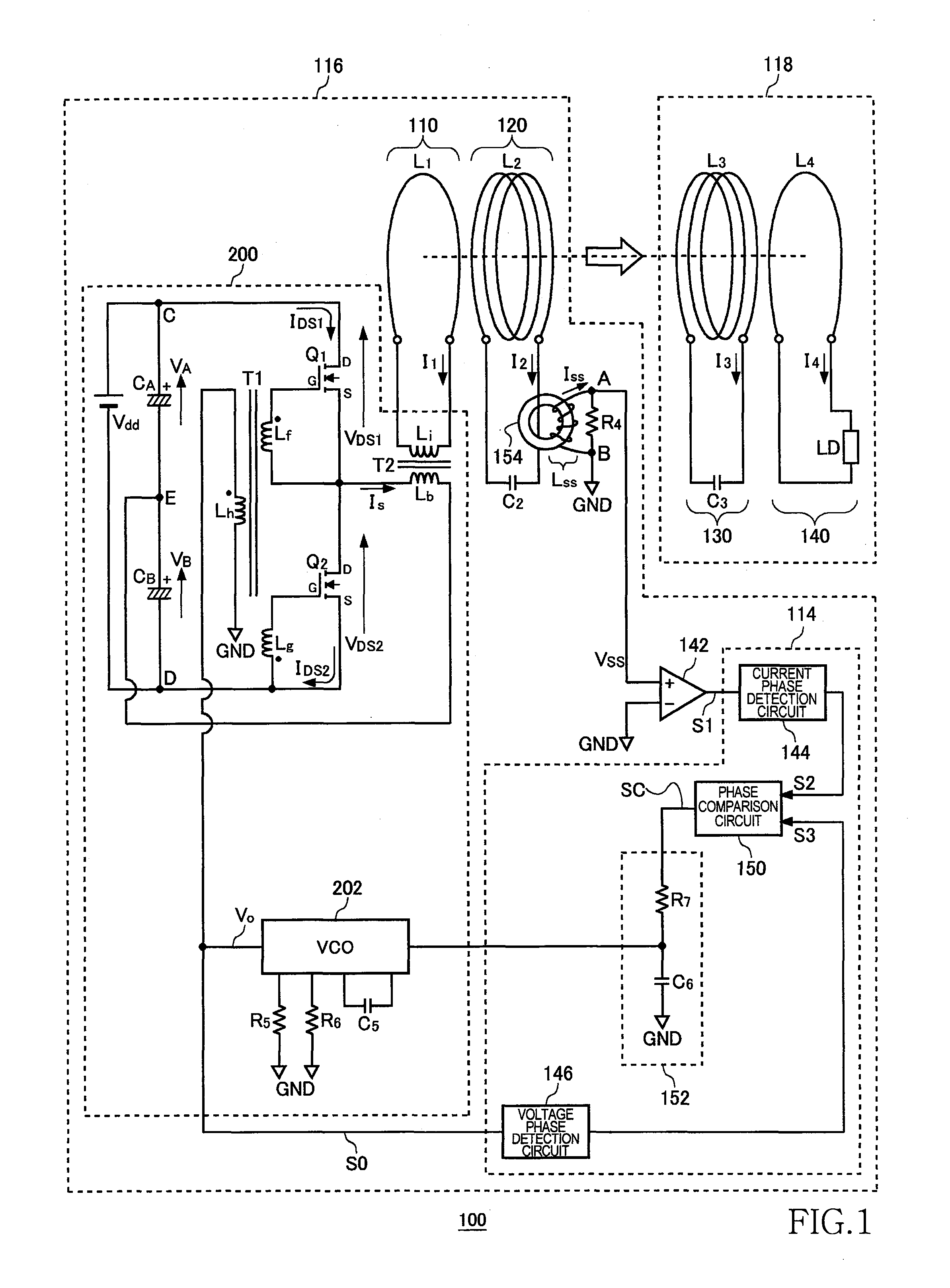
[0048]FIG. 1 is a system configuration view of a wireless power transmission system 100. The wireless power transmission system 100 includes a wireless power feeder 116 and a wireless power receiver 118. The wireless power feeder 116 includes, as basic components, a power transmission control circuit 200, an exciting circuit 110, a feeding coil circuit 120, and phase detection circuit 114. The wireless power receiver 118 includes a receiving coil circuit 130, and a loading circuit 140.

[0049]A distance of about 0.2 to 1.0 m is provided between a feeding coil L2 of the feeding coil circuit 120 and a receiving coil L3 of the receiving coil circuit 130. The wireless power transmission system 100 mainly aims to feed AC power from the feeding coil L2 to receiving coil L3 by wireless. The wireless power transmission system 100 according to the present embodiment is assu...


PUM

PropertyMeasurementUnit
distanceaaaaaaaaaa
resonance frequency fraaaaaaaaaa

Abstract

Power is fed from a feeding coil L2 to a receiving coil L3 by magnetic resonance. A VCO alternately turns ON / OFF switching transistors Q1 and Q2 at a drive frequency fo, whereby AC current is fed to the feeding coil L2, and then the AC current is fed from the feeding coil L2 to the receiving coil L3. A phase detection circuit detects a phase difference between the current phase and voltage phase, and the VCO adjusts the drive frequency fo such that the phase difference becomes zero. In a current phase detection circuit and a voltage phase detection circuit, detection values of the current and voltage phases can be changed, respectively and intentionally.

Description

BACKGROUND OF THE INVENTION[0001]1. Field of the Invention[0002]The present invention relates to a wireless AC power feeding and, more particularly, to power control thereof.[0003]2. Description of Related Art[0004]A wireless power feeding technique of feeding power without a power cord is now attracting attention. The current wireless power feeding technique is roughly divided into three: (A) type utilizing electromagnetic induction (for short range); (B) type utilizing radio wave (for long range); and (C) type utilizing resonance phenomenon of magnetic field (for intermediate range).[0005]The type (A) utilizing electromagnetic induction has generally been employed in familiar home appliances such as an electric shaver; however, it can be effective only in a short range of several centimeters. The type (B) utilizing radio wave is available in a long range; however, it cannot feed big electric power. The type (C) utilizing resonance phenomenon is a comparatively new technique and is...

Claims


Application Information

Patent Timeline
Patent Type & Authority Patents(United States)
IPC IPC(8): H01F27/42H01F37/00H01F38/00H02M7/48
CPCH05B37/00H02J5/005H05B47/10H02J50/12
Inventor URANO, TAKASHI
Owner TDK CORPARATION
Why Eureka
Try Eureka