Motor driver and method of controlling the same

a technology of motor drivers and motors, which is applied in the direction of dynamo-electric motors/converters, emergency protection arrangements for automatic disconnection, starter details, etc., can solve the problems of increasing loss, causing harmonization, and demagnetizing the permanent magnet motor

Active Publication Date: 2013-11-12
DENSO CORP
View PDF12 Cites 16 Cited by
  • Summary
  • Abstract
  • Description
  • Claims
  • Application Information

AI Technical Summary

Benefits of technology

[0012]The carrier frequency control device may increase the carrier frequency when the magnet temperature detected by the magnet temperature detection device exceeds the threshold value.
[0016]According to another aspect of the invention, a method of controlling a motor driver that receives electric power supply from a power source to drive a permanent magnet motor and that includes an inverter that has a switching device and performs electric power conversion between the power source and the permanent magnet motor by switching the switching device. The method includes: detecting a magnet temperature of the permanent magnet motor, setting a threshold value of the magnet temperature corresponding to the desired output of the permanent magnet motor, based on a predetermined relation between an output from the permanent magnet motor and a critical temperature, up to which demagnetization in the permanent magnet motor is not caused; and when the detected magnet temperature exceeds the threshold value, changing a carrier frequency, at which the switching device is switched, in such a manner that a ripple current superimposed on a motor current that flows through the permanent magnet motor is reduced.
[0017]The step of changing the carrier frequency may increase the carrier frequency when the detected magnet temperature exceeds the threshold value.

Problems solved by technology

When the ripple current increases, in the permanent magnet motor, harmonic loss is caused because the magnetic flux density therein includes harmonic components.
In particular, when a rare-earth permanent magnet is used, the electrical conductivity is relatively high and therefore, there is a possibility that eddy currents are generated in the permanent magnet and increase the loss.
Such increase in the eddy-current loss increases the magnet temperature and thus causes demagnetization in the permanent magnet motor.
Due to the occurrence of such demagnetization, a problem can arise that the operational efficiency (rotation efficiency and power generation efficiency) is reduced in the permanent magnet motor.

Method used


Image

  • Motor driver and method of controlling the same
  • Motor driver and method of controlling the same
  • Motor driver and method of controlling the same

Examples


first embodiment

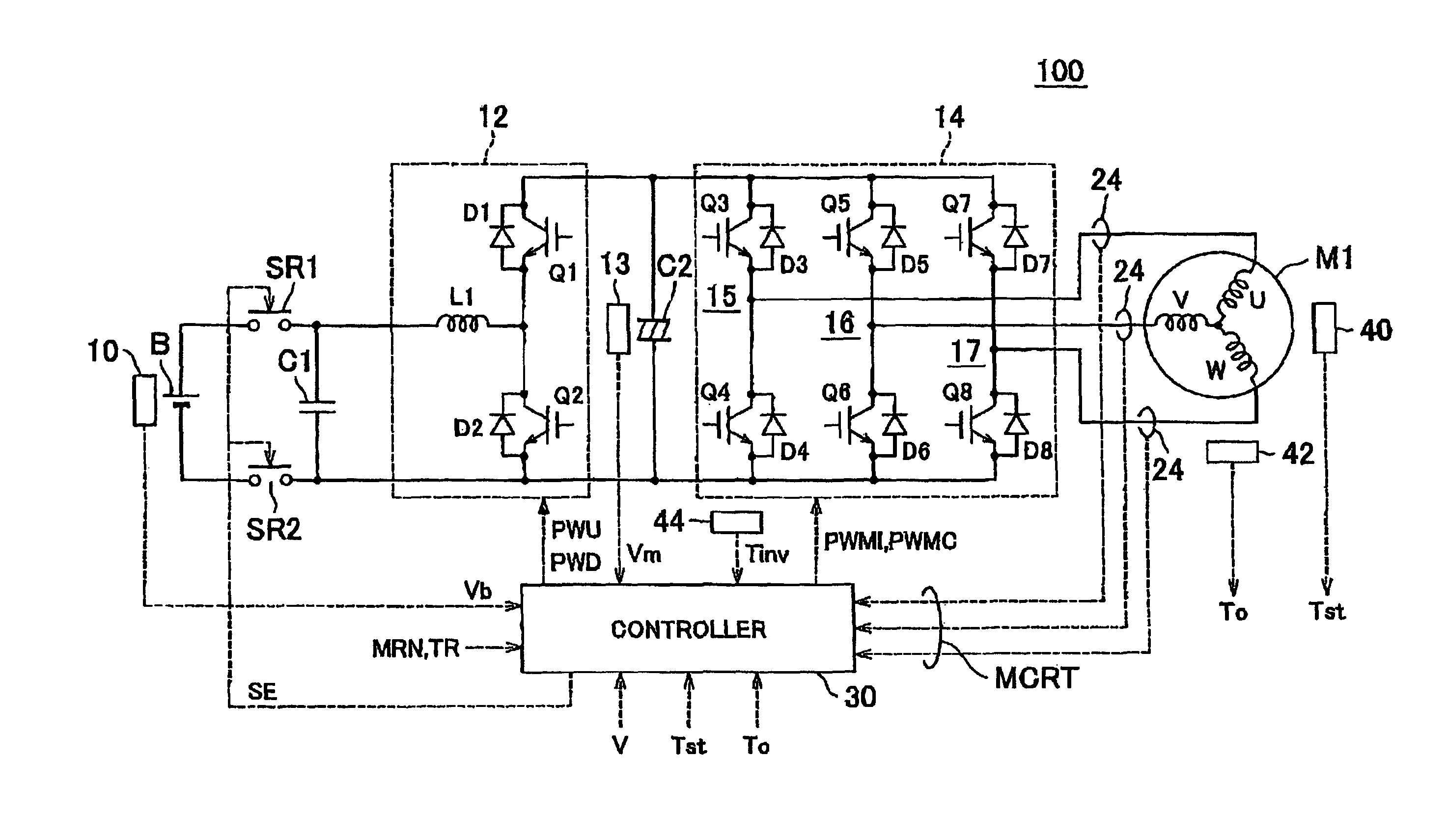
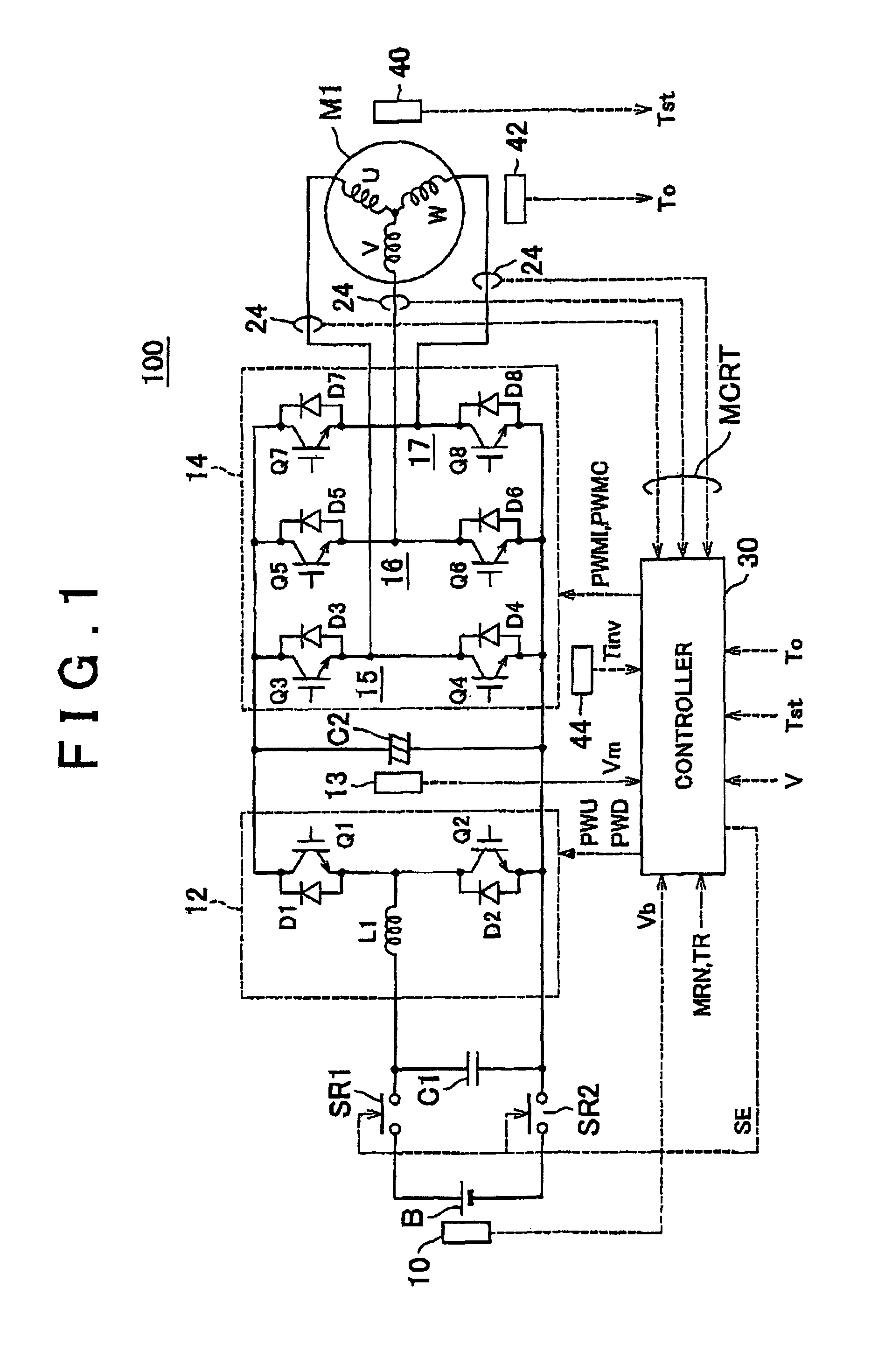
[0036]FIG. 1 is a schematic block diagram of a motor driver according to a first embodiment of the invention.

[0037]Referring to FIG. 1, the motor driver 100 includes a battery B, voltage sensors 10 and 13, electric current sensors 24, system relays SR1 and SR2, capacitors C1 and C2, a boost converter 12, an inverter 14, temperature sensors 40, 42, 44, and a controller 30.

[0038]A permanent magnet motor M1 is a three-phase alternating-current synchronous motor, which includes a U-phase coil, a V-phase coil, and a W-phase coil. The permanent magnet motor M1 is a drive motor that produces the torque for driving wheels of a hybrid vehicle or an electric vehicle. The permanent magnet motor M1 functions as an electricity generator that is driven by an engine and functions as an electric motor for the engine. For example, the permanent magnet motor M1 may be incorporated into a hybrid vehicle so as to be able to start the engine.

[0039]The temperature sensor 40 detects the temperature Tst of...

second embodiment

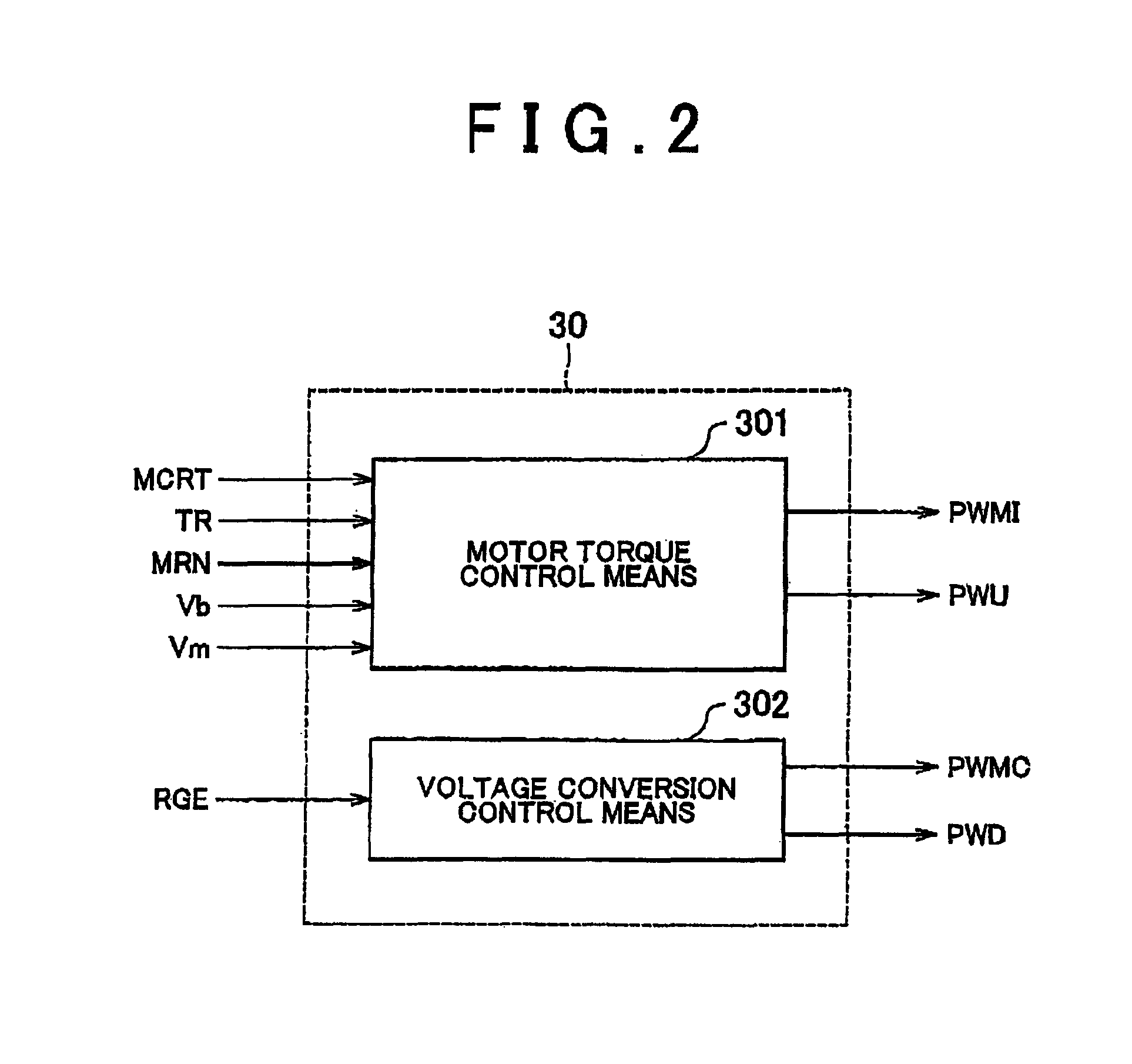
[0097]FIG. 9 is a functional block diagram of a motor torque control means 301A according to a second embodiment of the invention. The motor torque control means 301A shown in FIG. 9 is obtained by replacing the inverter PWM signal conversion section 52 and the carrier frequency control section 56 of the motor torque control means 301 shown in FIG. 3 by an inverter PWM signal conversion section 52A and a carrier frequency control section 56A, respectively. For this reason, repetitive detailed description of the other common portions is not given.

[0098]Referring to FIG. 9, the carrier frequency control section 56A receives the magnet temperature Tm from the magnet temperature detection section 54, receives the device temperature Tinv of the inverter 14 from the temperature sensor 44 (FIG. 1), and receives a vehicle speed V from the vehicle speed sensor (not shown). The carrier frequency control section 56A generates the signals CHG1, CHG2, and CHG3 for changing the carrier frequency ...


PUM


Abstract

A controller controls switching of IGBT devices of an inverter according to the desired output of the permanent magnet motor. The controller includes: a magnet temperature detection device that detects the magnet temperature of the permanent magnet motor based on the output of a temperature sensor; a setting device that sets a threshold value of the magnet temperature corresponding to the desired output of the permanent magnet motor, based on a predetermined relation between the output from the permanent magnet motor and a critical temperature, up to which demagnetization in the permanent magnet motor is not caused; and a carrier frequency control device that, when the magnet temperature detected by the magnet temperature detection device exceeds the threshold value, changes the carrier frequency, at which the IGBT devices are switched, such that a ripple current superimposed on a motor current that flows through the permanent magnet motor is reduced.

Description

[0001]This is a 371 national phase application of PCT / 82009 / 007073 filed 8 Oct. 2009, claiming priority to Japanese Patent Application No. 2008-263135 filed 9 Oct. 2008, the contents of which are incorporated herein by reference.BACKGROUND OF THE INVENTION[0002]1. Field of the Invention[0003]The invention relates to a motor driver and a method of controlling the motor driver, and in particular to a motor driver that drives a permanent magnet motor and a method of controlling the motor driver.[0004]2. Description of the Related Art[0005]Typically, in a vehicle, such as an electric vehicle or a hybrid vehicle, the driving force generated by electric energy is obtained by converting the direct current voltage supplied from a high-voltage power source into a three-phase alternating-current power with the use of an inverter and rotating the three-phase alternating-current motor with the use of the alternating-current power. When the vehicle is decelerated, inversely, the regenerated ener...

Claims


Application Information

Patent Timeline
Patent Type & Authority Patents(United States)
IPC IPC(8): H02P6/10B60L9/18H02P6/06H02P6/08H02P6/12
CPCH02P6/002H02P25/021H02P29/0038H02P29/02H02P6/28H02P25/024H02P29/50
Inventor HAYASHI, KAZUHITOSUHAMA, MASAYOSHI
Owner DENSO CORP
Why Eureka
Try Eureka