Device for testing high-voltage equipment

a high-voltage equipment and device technology, applied in the direction of measurement devices, power conversion systems, instruments, etc., can solve the problem that the testing system would no longer be roadworthy with respect, and achieve the effect of high reactive power, simple and effective, and equivalent effectiveness

Active Publication Date: 2013-11-19
MASCHFAB REINHAUSEN GEBR SCHEUBECK GMBH & CO KG
View PDF12 Cites 2 Cited by
  • Summary
  • Abstract
  • Description
  • Claims
  • Application Information

AI Technical Summary

Benefits of technology

[0009]The general inventive idea is to shift the required potential separation for suppressing asymmetrical interference to the input side of the static frequency converter, thus to the line side. The previous potential separation on the load side by the filter transformer installed in the sine-wave filter required a relatively large transformer. The reason for this is that the parts of the static frequency converter on the line side are responsible only for the provision of the active power of the testing system. The parts of the static frequency converter on the load side, moreover, has to be able to provide the high reactive power required for the testing. Therefore, the parts of the static is converter on the load side are usually dimensioned for a higher capacity than the one on the line side (typically 40% capacity on the line side, 100% capacity on the load side). In case of a significant increase of the apparent power on the load side, a correspondingly large filter transformer would have to be used. In this case, the testing system would no longer be roadworthy with respect to the permissible total weights and axle load distributions governed by the road traffic regulations. By shifting, according to the invention, the potential separation to the line side of the static frequency converter, a mobile testing system having an equivalent effectiveness and comprising a transformer that only has to be dimensioned according to the active power is sufficient. Therefore, with this measure, the conformity of the permissible total weight and axle load distribution can be ensured in a particular simple and effective manner.
[0010]Thus, the actual filter no longer consists of a filter transformer and grounded filter capacitors interconnected in a star connection as known from DE 10 2007 059 289.4-35, but consists only of inductors connected in series to the outputs of the static frequency converter followed by grounded filter capacitors connected in a star connection that filters out asymmetrical interference between the outer conductors and ground. This filtering is possible only because of the potential separation of the transformer used on the line side. Here, between primary and secondary sides of the transformer used on the line side, a grounded electrostatic shield is provided that also contributes to the dissipation of asymmetrical interference.
[0011]It is advantageous if the static frequency converter, the transformer on the line side, and the load-side sine-wave filter with the filter capacitors interconnected in star connection are enclosed in a control cabinet so that no asymmetrical interference reach the transformer subjected to the test.
[0013]By shifting, according to the invention, the transformer for the testing system to the line side, the entire installation has a total weight that is significantly reduced with respect to the prior art. Moreover, with the new testing system, the passive compensation unit can also be eliminated to further contribute to the weight reduction.

Problems solved by technology

In this case, the testing system would no longer be roadworthy with respect to the permissible total weights and axle load distributions governed by the road traffic regulations.

Method used


Image

  • Device for testing high-voltage equipment
  • Device for testing high-voltage equipment
  • Device for testing high-voltage equipment

Examples


Embodiment Construction

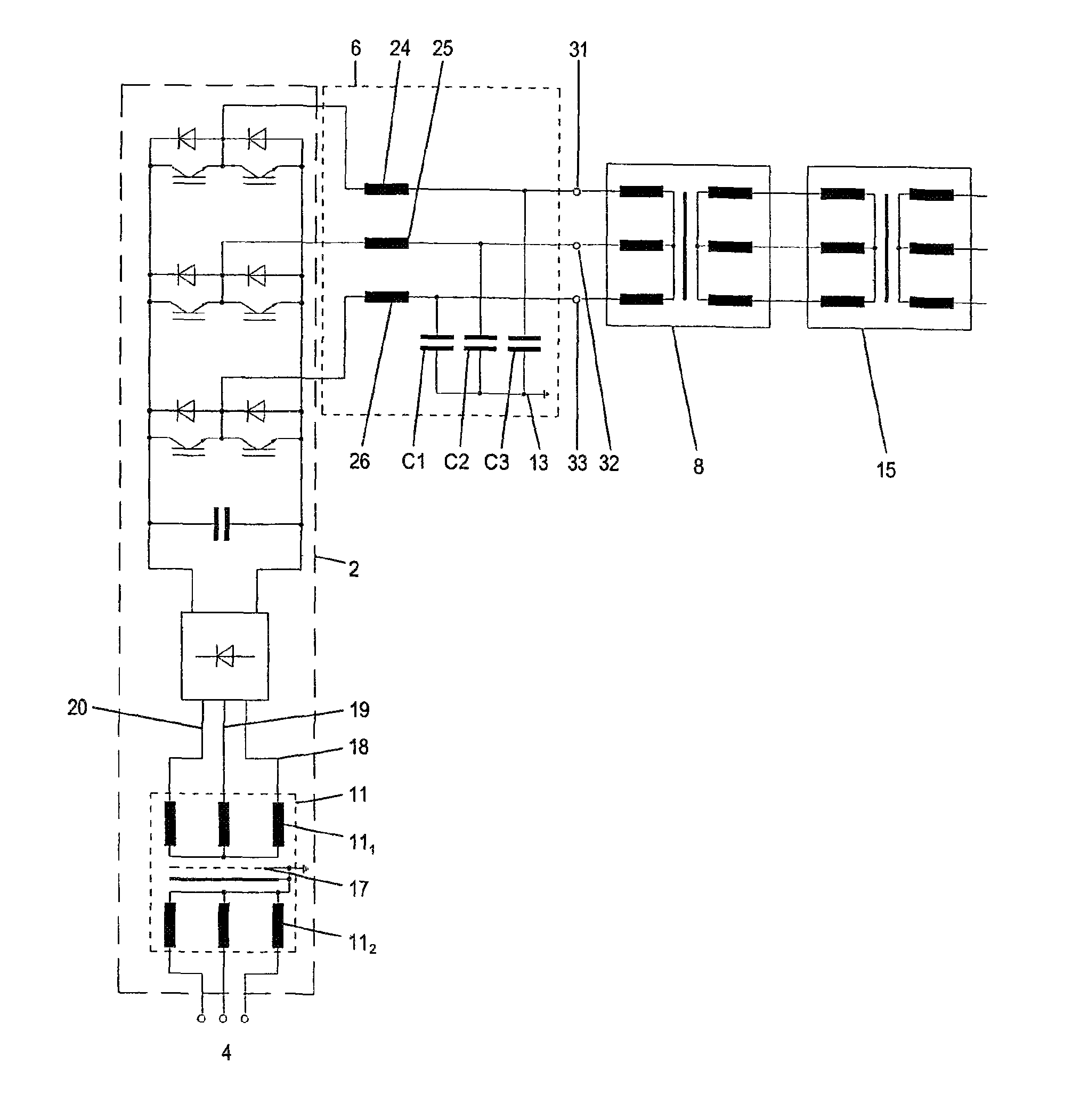
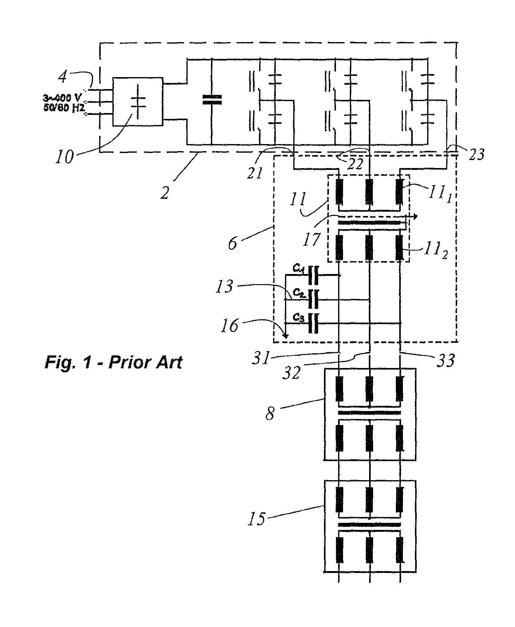
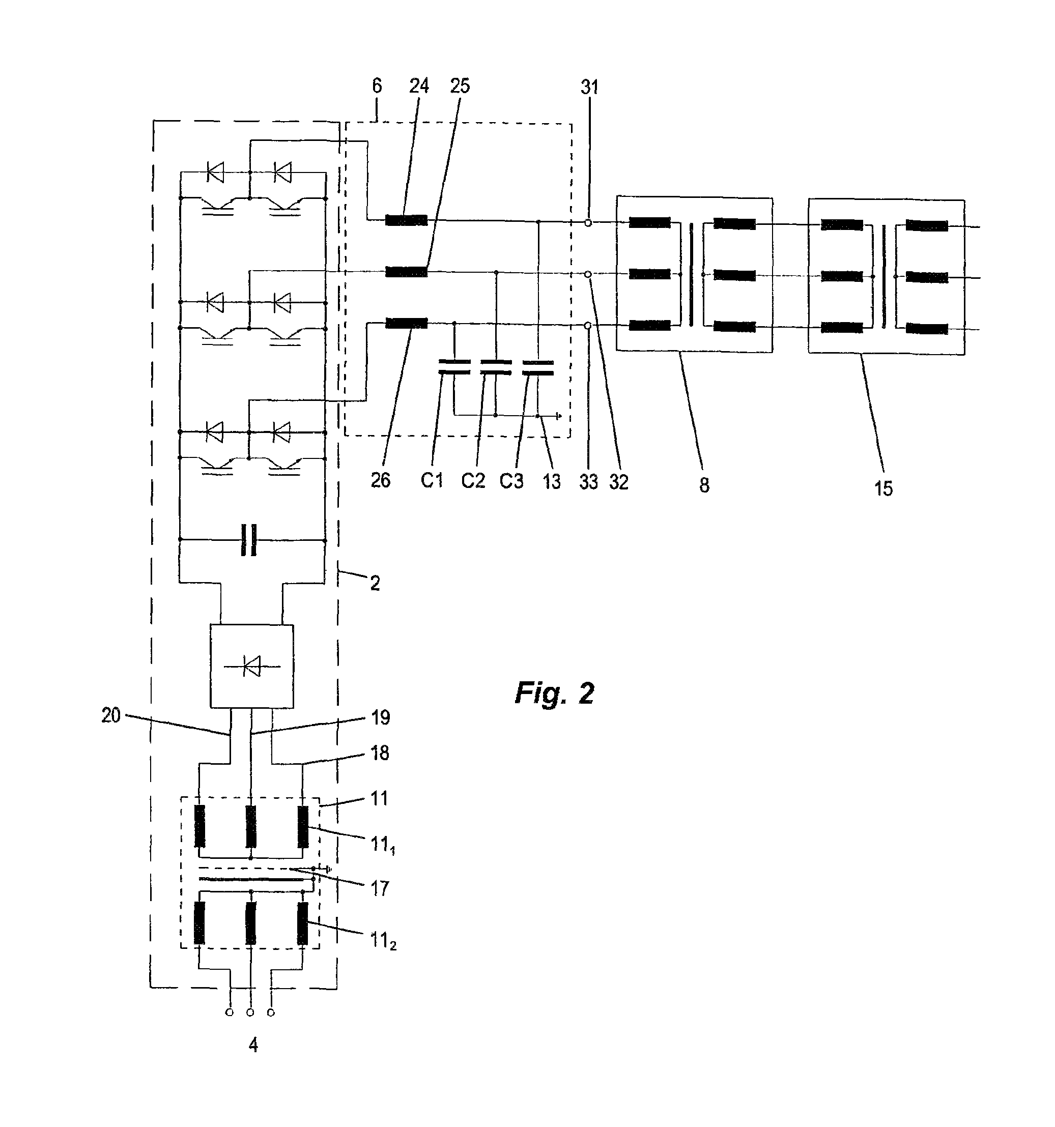
[0019]FIG. 1 is a circuit diagram of an apparatus for testing high-voltage equipment, which diagram is described in DE 10 2007 059 289, but not pre-published. A static frequency converter 2 is supplied from line 4 with alternating current voltage that arrives first at a rectifier 10. In addition, the frequency converter 2 has a first output 21, a second output 22 and a third output 23. The static frequency converter 2 is a voltage intermediate circuit converter with a digital control and closed-loop control. The outputs 21, 22 and 23 of the static frequency transformer 2 are fed to a filter 6, in particular to a primary side 111 of a filter transformer 11. The filter transformer 11 comprises the primary side 111 and a secondary side 112. The secondary side 112 of the filter transformer 11 is connected to the filter capacitors C1, C2 and C3 that are arranged in a star connection 13. The star point resulting from the star connection, in turn, is connected to ground 16. The filter tran...


PUM


Abstract

An apparatus for testing a high-voltage equipment transformer or inductor has a filter transformer having a primary side connectable to line and a secondary side and a grounded electrostatic shield between the primary and secondary sides. A static frequency converter has a plurality of inputs connected to the filter-transformer outputs and a plurality of outputs. Respective capacitors each have one side connected to a respective one of the converter outputs and an opposite side connected star-fashion to a common ground. A matching transformer has a plurality of inputs connected to the capacitors and a plurality of outputs connectable to the transformer or inductor to be tested.

Description

CROSS REFERENCE TO RELATED APPLICATIONS[0001]This application is the US-national stage of PCT application PCT / EP2010 / 002426 filed 21 Apr. 2010, published 9 Dec. 2010 as WO2010 / 139382, and claiming the priority of German patent application 102009023713.5 itself filed 3 Jun. 2009.FIELD OF THE INVENTION[0002]The present invention relates to an apparatus for testing high-voltage equipment, in particular power transformers or inductors.BACKGROUND OF THE INVENTION[0003]In this context, it has proved to be advantageous to use static frequency converters instead of rotary converters because static frequency converters have clear advantages over rotary converters with respect to dynamic, wear, weight and availability. Frequency converters have to generate a sinusoidal symmetrical alternating current voltage that, in addition, has a distortion factor of less than 5%. For testing the insulation systems of power transformers, induced voltage testing is used in which partial discharge measuremen...

Claims


Application Information

Patent Timeline
Patent Type & Authority Patents(United States)
IPC IPC(8): G01R31/06
CPCG01R31/027G01R31/1227G01R31/62H02M1/123
Inventor ANNOWSKY, RENETHIEDE, ANDREAS
Owner MASCHFAB REINHAUSEN GEBR SCHEUBECK GMBH & CO KG
Why Eureka
Try Eureka