Extended depth of field for image sensor

an image sensor and depth of field technology, applied in the field of electronic image capture systems, can solve the problems of limiting the utility of each approach, unable to compensate for the problem of no added pixel resolution, and the solution cannot be used in most types of consumer photography or casual photography applications, so as to achieve the effect of improving the depth of field of imaging devices

Active Publication Date: 2013-11-19
OMNIVISION TECH INC
View PDF28 Cites 52 Cited by
  • Summary
  • Abstract
  • Description
  • Claims
  • Application Information

AI Technical Summary

Benefits of technology

[0011]It is an object of the present invention to advance the art of digital imaging and offer improved depth of field for imaging devices that use electronic imaging sensors. With this object in mind, the present invention provides a method for forming an image, implemented at least in part by a data processing apparatus including the steps of obtaining a first image of a scene from a first subset of pixels in an image sensor array at a first f / # setting, adjusting the imaging optics that obtain light from the scene to a second f / # setting, obtaining a second image of the scene from a second subset of pixels in the image sensor array, and forming a composite image by combining image data from at least the first and second images.

Problems solved by technology

This is true, for example, for parts of the image that are optically out of focus; no added pixel resolution can compensate for this problem.
Although some measure of increase to depth of field is provided by each of these conventional approaches, there are drawbacks that limit the utility of each approach.
This solution can be unworkable for most types of consumer photography or casual photography applications.
Wavefront coding requires detailed characterization of the point-spread function (psf) of camera optics and is computationally intensive and complex, typically requiring additional circuitry for frame memory and processing, making this an impractical solution, particularly for video image processing.
Plenoptic image capture devices also have inherent computational complexity and require component packaging designs that may not be easily adapted to the narrow profile of hand-held devices such as cellphones and the like.
Thus, it can be seen that although methods exist for enhancing or extending the depth of field of an image sensor and its attendant optical system, these methods may be impractical for many types of portable and hand-held imaging apparatus.

Method used


Image

  • Extended depth of field for image sensor
  • Extended depth of field for image sensor
  • Extended depth of field for image sensor

Examples


Embodiment Construction

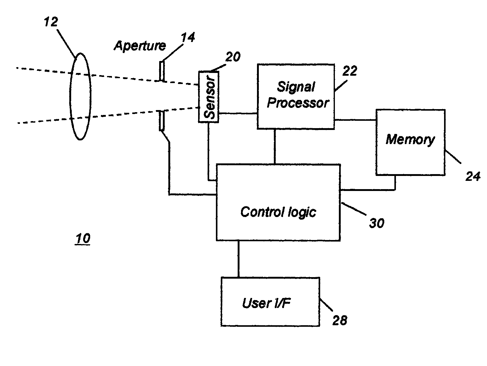
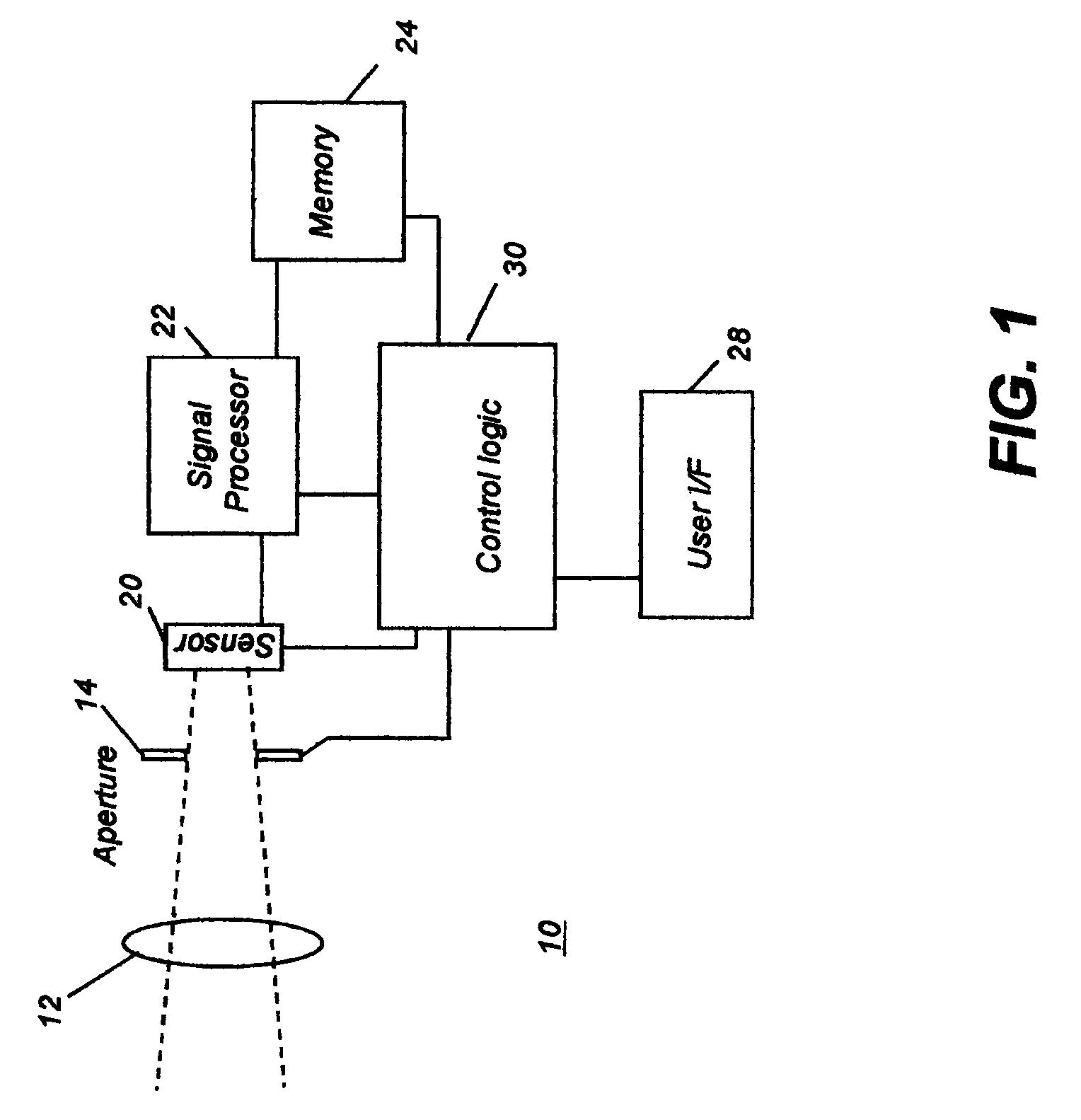
[0025]Because digital imaging devices and related circuitry for signal capture and correction and for exposure control are well known, the present description is directed more specifically to elements and operation related to the present invention. Elements not specifically shown or described herein are selected from those known in the art.

[0026]Figures shown and described herein are provided in order to illustrate key principles of operation of the present invention and are not drawn with intent to show actual size or scale. Some exaggeration may be necessary in order to emphasize relative spatial relationships or principles of operation.

[0027]Certain aspects of the embodiments to be described are controlled by instructions provided from software, under control of a data processing apparatus, such as a computer, microprocessor, or other type of control logic processor. Given the system as shown and described according to the invention in the following disclosure, software not speci...


PUM


Abstract

A method for forming an image, implemented at least in part by a data processing apparatus, by obtaining a first image of a scene from a first subset of pixels in an image sensor array at a first f / # setting, adjusting the imaging optics that obtain light from the scene at a second f / # setting, obtaining a second image of the scene from a second subset of pixels in the image sensor array, and forming a composite image by combining image data from at least the first and second images.

Description

FIELD OF THE INVENTION[0001]The present invention relates to electronic image capture systems and more particularly relates to an apparatus and readout method for an image sensor array that provides an image having an extended depth of field.BACKGROUND OF THE INVENTION[0002]Electronic image sensors such as charge coupled device (CCD) image sensors and active pixel sensor (APS) devices are used in many types of electronic imaging systems for generating an electronic representation of a visual image. APS devices, often fabricated in a Complementary Metal Oxide Semiconductor process, are also referred to as CMOS sensors. Typically, these image sensors include a number of light-sensitive pixels (that is, picture elements) arranged in a regular two-dimensional pattern or array of rows and columns, with each individual pixel providing a signal based on the light level of the portion of a scene image projected onto the pixel by a lens.[0003]As a result of ongoing improvements in fabricatio...

Claims


Application Information

Patent Timeline
Patent Type & Authority Patents(United States)
IPC IPC(8): H04N5/225H04N9/04G03B7/00H04N5/235
CPCH04N5/232H04N5/23232H04N5/2355H04N5/2356H04N5/238H04N5/3454H04N5/3532H04N23/60H04N23/951H04N23/743H04N23/741H04N23/75H04N25/443H04N25/531H04N25/134
Inventor GUIDASH, ROBERT M.
Owner OMNIVISION TECH INC
Why Eureka
Try Eureka