
System and method for material decomposition optimization in image domain

a material decomposition optimization and image domain technology, applied in the field of diagnostic imaging, can solve the problems of system complexity and additional cost of operation

Active Publication Date: 2013-11-19
GENERAL ELECTRIC CO
View PDF3 Cites 17 Cited by
  • Summary
  • Abstract
  • Description
  • Claims
  • Application Information

AI Technical Summary

Problems solved by technology

However, such systems typically include additional cost and complexity of operation in order separate and distinguish energy content of each received x-ray photon.

Method used


Image

  • System and method for material decomposition optimization in image domain
  • System and method for material decomposition optimization in image domain
  • System and method for material decomposition optimization in image domain

Examples


Embodiment Construction

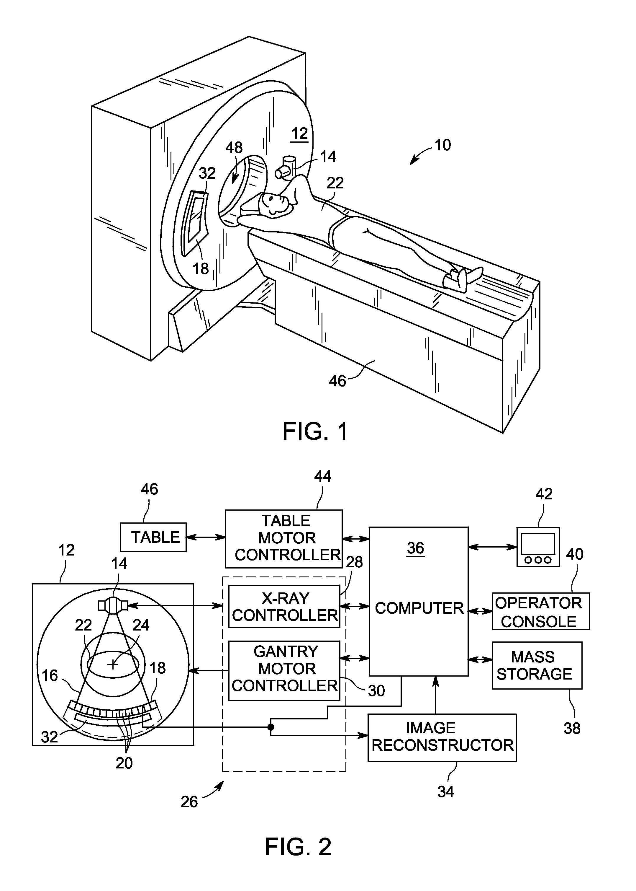
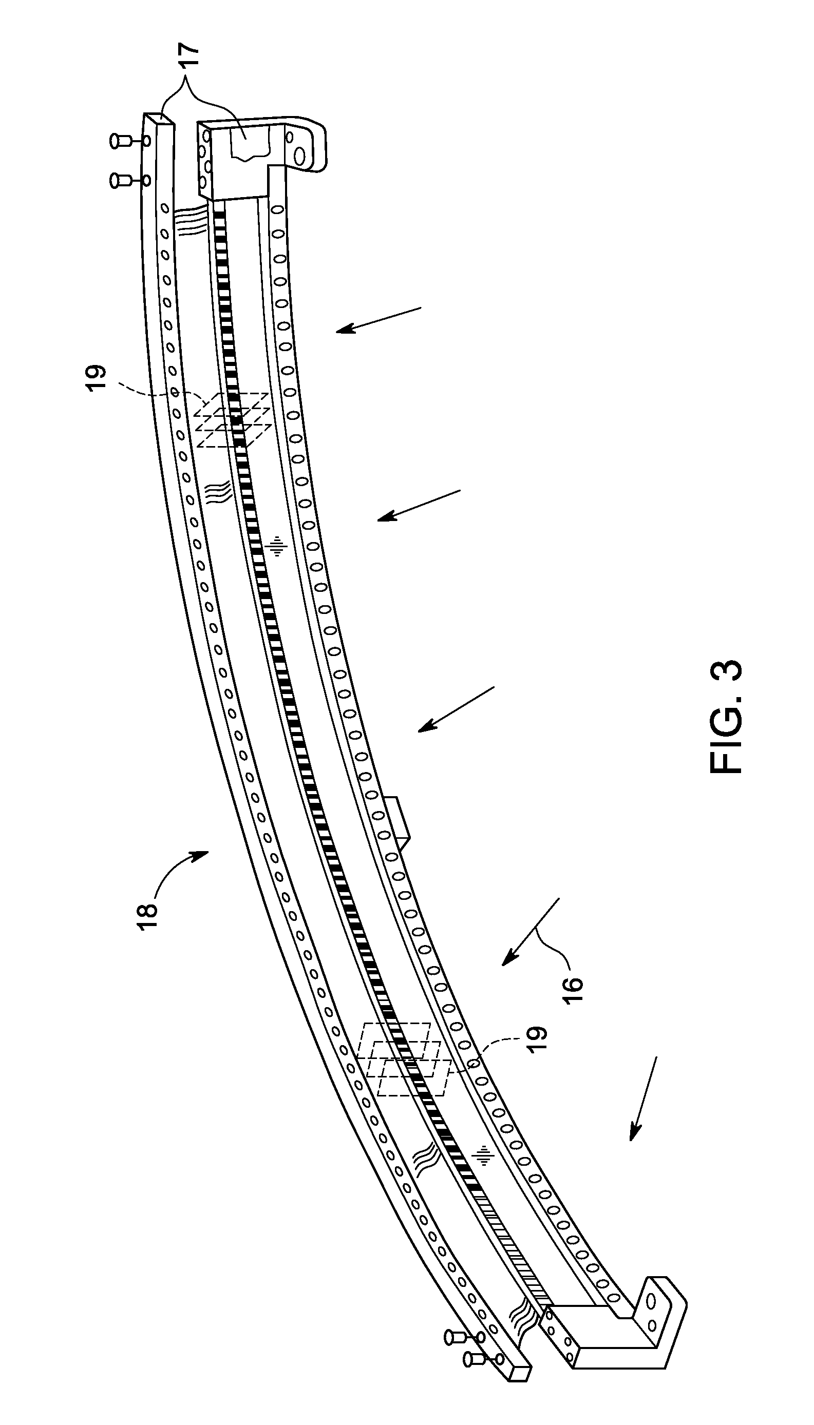
[0028]Diagnostics devices comprise x-ray systems, magnetic resonance (MR) systems, ultrasound systems, computed tomography (CT) systems, positron emission tomography (PET) systems, ultrasound, nuclear medicine, and other types of imaging systems. Applications of x-ray sources comprise imaging, medical, security, and industrial inspection applications. However, it will be appreciated by those skilled in the art that an implementation is applicable for use with single-slice or other multi-slice configurations. Moreover, an implementation is employable for the detection and conversion of x-rays. However, one skilled in the art will further appreciate that an implementation is employable for the detection and conversion of other high frequency electromagnetic energy.

[0029]The operating environment of embodiments of the invention is described with respect to a sixty-four-slice computed tomography (CT) system. However, it will be appreciated by those skilled in the art that embodiments of...


PUM

PropertyMeasurementUnit
concentrationaaaaaaaaaa
concentrationsaaaaaaaaaa
CTaaaaaaaaaa

Abstract

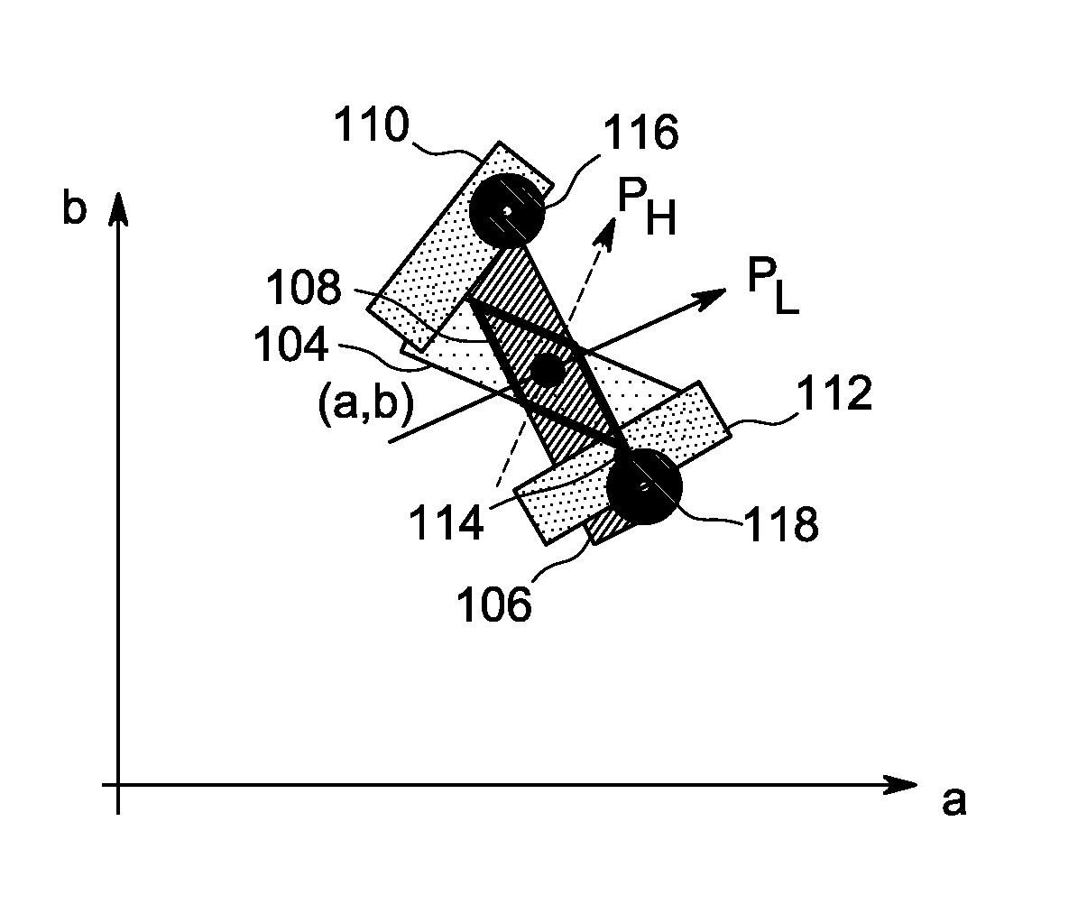
A system and method for material decomposition optimization in the image domain include a non-transitory computer readable medium has stored thereon a sequence of instructions which, when executed by a computer, causes the computer to access a reconstructed basis material image. For a first voxel of the reconstructed basis material image, the instructions also cause the computer to optimize a concentration of a pair of materials (a,b) in the first voxel exclusively in the image domain and based on a first probability based on random perturbations and a second probability based on random perturbations. The optimization is further based on a third probability based on known materials and a fourth probability based on concentrations of the pair of materials in a pair of voxels neighboring the first voxel.

Description

BACKGROUND[0001]Embodiments of the invention relate generally to diagnostic imaging and, more particularly, to a system and method of material decomposition optimization in the image domain.[0002]Typically, in computed tomography (CT) imaging systems, an x-ray source emits a fan-shaped or cone-shaped beam toward a subject or object, such as a patient or a piece of luggage. Hereinafter, the terms “subject” and “object” shall include anything capable of being imaged. The beam, after being attenuated by the subject, impinges upon an array of radiation detectors. The intensity of the attenuated beam radiation received at the detector array is typically dependent upon the attenuation of the x-ray beam by the subject. Each detector element of the detector array produces a separate electrical signal indicative of the attenuated beam received by each detector element. The electrical signals are transmitted to a data processing system for analysis, which ultimately produces an image.[0003]Ge...

Claims


Application Information

Patent Timeline
Patent Type & Authority Patents(United States)
IPC IPC(8): G06K9/00G21K1/12A61B6/00G01N23/00H05G1/60
CPCG06T11/008H04B1/1638G06T2211/408
Inventor DE MAN, BRUNO KRISTIAAN BERNARDHSIEH, JIANGCHANDRA, NAVEENPACK, JED DOUGLASFAN, JIAHUA
Owner GENERAL ELECTRIC CO
Learn More