Procedure for design and production of implant-based frameworks for complex dental prostheses

a dental prosthesis and implant technology, applied in the field of dental prosthesis framework, can solve the problems of high precision, time-consuming and inefficient, and long and labor-intensive process of lost wax method

Active Publication Date: 2013-11-26
LAYERWISE
View PDF25 Cites 80 Cited by
  • Summary
  • Abstract
  • Description
  • Claims
  • Application Information

AI Technical Summary

Problems solved by technology

Although these processes lead to high precision, they are time consuming and inefficient.
The lost wax method is a lengthy and labour-intensive process and comprises many manual steps (fabricating the wax pattern, embedding the wax pattern, burning out the wax material, metal casting, post-processing).
However, this milling process is also time consuming because of the lengthy calculation of the tool paths and because of the lengthy manual finishing needed to obtain an accurate fit of the framework.
Moreover, most of the material is wasted and spatial restrictions limit the production of complex shapes.

Method used


Image

  • Procedure for design and production of implant-based frameworks for complex dental prostheses
  • Procedure for design and production of implant-based frameworks for complex dental prostheses
  • Procedure for design and production of implant-based frameworks for complex dental prostheses

Examples


example 1

Production of a Framework in Stainless Steel Using SLPP

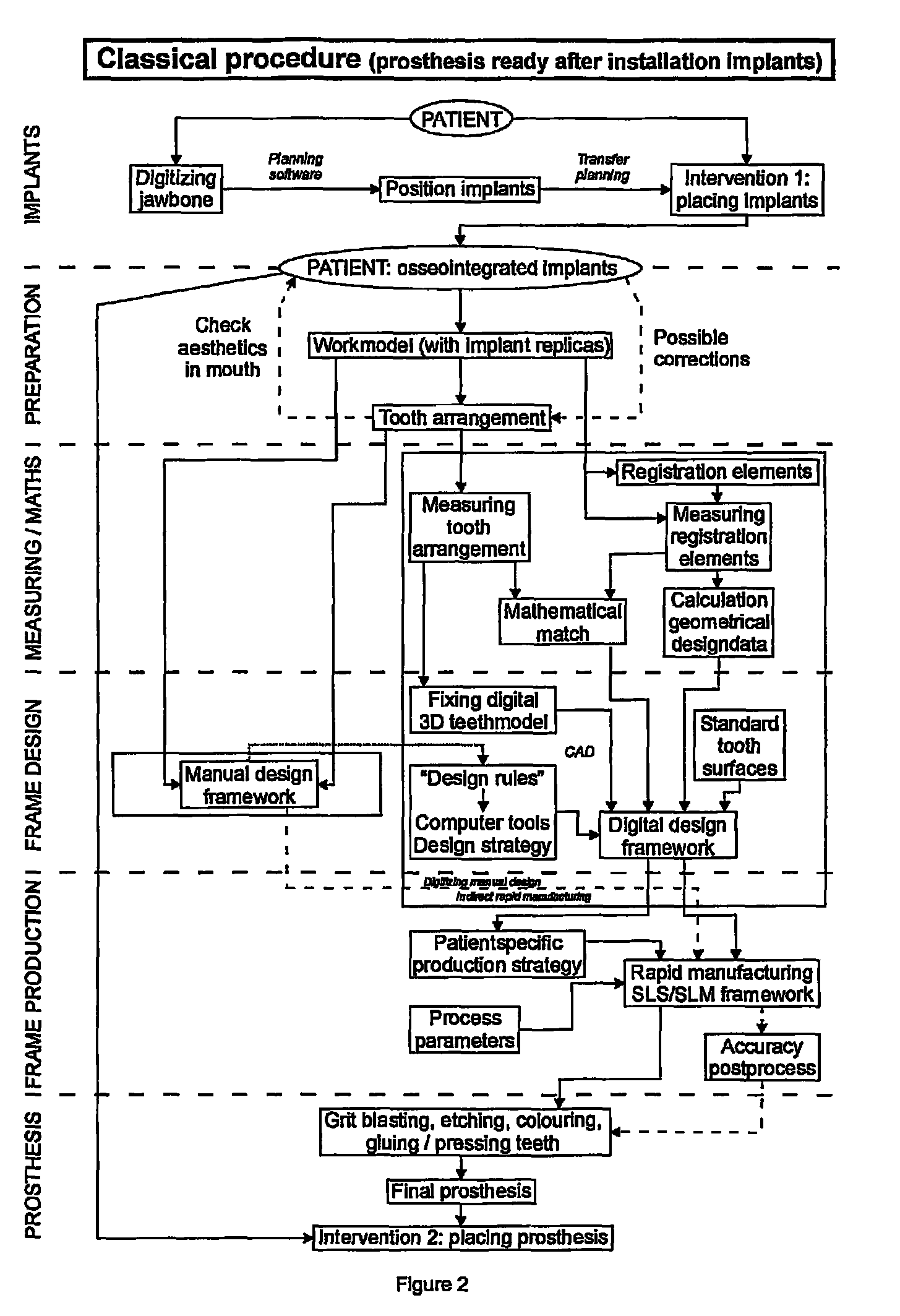
[0072]A framework for a certain patient was designed and produced in stainless steel by means of a SLPP process according to the method as was described for the Classical procedure.

[0073]This SLPP process makes use of stainless steel powder (diameter about 60 μm) coated by polymer material. During the SLPP process the polymer material was melted by the 100 W CO2 laser and the melted polymer bound the stainless steel powder. During a furnace cycle the polymer is burned out and the green part, made by the SLPP process, is infiltrated with bronze to get a full dense framework. The laser, material, environment and scan parameters (table 1) were optimized for this SLPP process. Special attention is paid to the setting of scaling factors and offset factors to obtain high process accuracy. A general and combined process parameter is the energy density. The energy density needed for the accurate production of the framework by means of t...

example 2

Production of a Framework in a Titanium-alloy Using SLPP

[0088]The Classical procedure has been applied to fabricate a framework in a titanium-alloy, namely Ti6Al4V, for a certain patient by means of a SLPP process. This Ti6Al4V framework was designed and produced according to the method described for the Classical procedure using an SLFM process. It has good mechanical as well as geometrical properties.

[0089]In contrast to the SLPP process of example 1 this SLPP process makes use of Ti6Al4V powder (diameter about 25 μm) with no polymer or other binder material. During this SLPP process the powder material is fully melted by the 100 W Nd-YAG laser (wave length 1064 nm). The laser can be used in continuous or in pulsed mode to produce the framework and the spot size on the build platform can be changed from 100 μm to 250 μm. This SLPP process allowed to produce a fully dense framework (over 99.98% density) in one single step without the use of a post-processing or an infiltration step...


PUM

PropertyMeasurementUnit
angleaaaaaaaaaa
mean gap sizeaaaaaaaaaa
tilt angleaaaaaaaaaa

Abstract

The present invention provides methods allowing the use of selective laser powder processing techniques for the production of medically acceptable prosthetic dental frameworks. The frameworks produced according to the present invention have high grade mechanical properties as well as a high accuracy.

Description

FIELD OF THE INVENTION[0001]The present invention relates to frameworks for dental prostheses produced using selective laser powder processing techniques as well as to a method for the production of such frameworks.BACKGROUND OF THE INVENTION[0002]A framework for a dental prosthesis (FIG. 1) (2) is the metal base structure of the prosthesis (1). It is supported by oral implants (4) placed in the jawbone (5) or by remaining teeth. Such framework is fixed to the jaw by screwing it on the implants or by cementing it on the remaining teeth. The framework supports the missing teeth (3) which are attached on the support surfaces on top of the framework. The prostheses are patient specific and have to meet strict requirements of accuracy to reach an optimal fit at the prosthesis-implant or prosthesis-tooth junction. To distribute forces evenly and to avoid high stresses in the jawbone causing the oral implants to loose and to diminish the risk for colonization of bacteria resulting in infe...

Claims


Application Information

Patent Timeline
Patent Type & Authority Patents(United States)
IPC IPC(8): A61C8/00G06F17/50G06F19/00A61C13/00B22F3/105B29C67/00G05B19/4099
CPCA61C13/0004A61C13/0018B22F3/1055B29C67/0077G05B19/4099A61C8/0048Y10T29/49567G05B2219/45167G05B2219/49018Y10T29/49995B29C67/0081B29C64/153B29C64/165B33Y80/00B33Y70/00Y02P10/25B22F10/28B22F10/47B22F10/25G16H20/40
Inventor KRUTH, JEAN-PIERRENAERT, IGNACEVANDENBROUCKE, BEN
Owner LAYERWISE
Why Eureka
Try Eureka