Subsea drilling

a technology for drilling wells and subsea, which is applied in the direction of tube shearing machines, sealing/packing, and borehole/well accessories, etc. it can solve the problems of inability to establish a well as the wellhead is installed, and achieve the effect of reducing the downtime for re-entry and facilitating shut down

Inactive Publication Date: 2013-11-26
QUANTUM LEAP TECH
View PDF36 Cites 3 Cited by
  • Summary
  • Abstract
  • Description
  • Claims
  • Application Information

AI Technical Summary

Benefits of technology

[0007]It is therefore an object of the present invention to provide a method of establishing a subsea well where the shut-off device is run-in with the drilling assembly so that the well is drilled and established on a single trip without the need to first drill and locate a wellhead, and incorporate measures in the shut-off device which facilitates shut down without using shear rams and also reduces downtime for re-entry.
[0041]This allows the subsea well to be initially ‘spudded’ so that the shut off device can be inserted into the sea floor easily. Such a method is required where the sea floor comprises harder stiffer soils e.g. North Sea and the East Coast of Canada. In this embodiment the section of larger casing may be a conductor having a shoe at an end thereof. In this way the shoe can be reciprocated in the well to aid entry of the conductor into the sea floor.
[0043]Preferably the method includes the step of activating a first seal at a lower end of the shut off device. This creates a seal between the casing string and the shut off device to prevent cutting returns from entering the shut off device. This first seal may be a low pressure seal.
[0053]Preferably the method also includes the step of reconnecting a casing string to the shut off device. In this way the well can be re-established by deploying a conventional wellhead connector attached to casing or a conventional riser. Reconnection on the alternative embodiment is now easier due to the controlled cutting of the casing without crushing the casing. Additionally the cutting does not have to take place under well pressure.
[0065]Preferably the one or more rams comprise pairs of shear rams located perpendicular to the throughbore and opposite each other. More preferably there are dual pairs of shear rams to provide a back-up if the first set fail. Advantageously the shear rams are as described in Applicants co-pending Application, GB 0512995.2. Such rams have a dual operation, first in crushing the tubular and secondly in severing the tubular. In this way they can reliably sever and seal through a tubular in which a further tubular is located.

Problems solved by technology

However, this arrangement is only acceptable for some situations where the vessel is moored in benign metocean conditions.
While this system addresses requirement for a subsea shut-off device it has the inherent disadvantage in the time taken to establish a well as the wellhead is installed before the subsea BOP is located and connected to the riser.

Method used


Image

  • Subsea drilling
  • Subsea drilling
  • Subsea drilling

Examples


Embodiment Construction

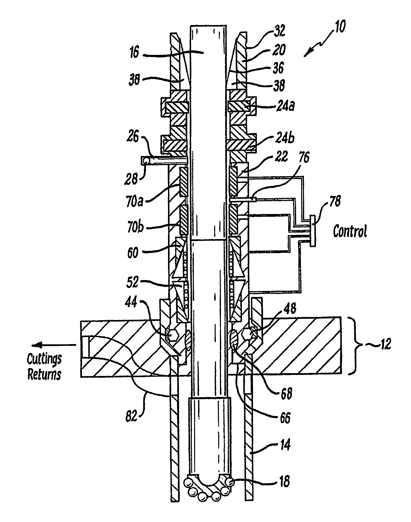
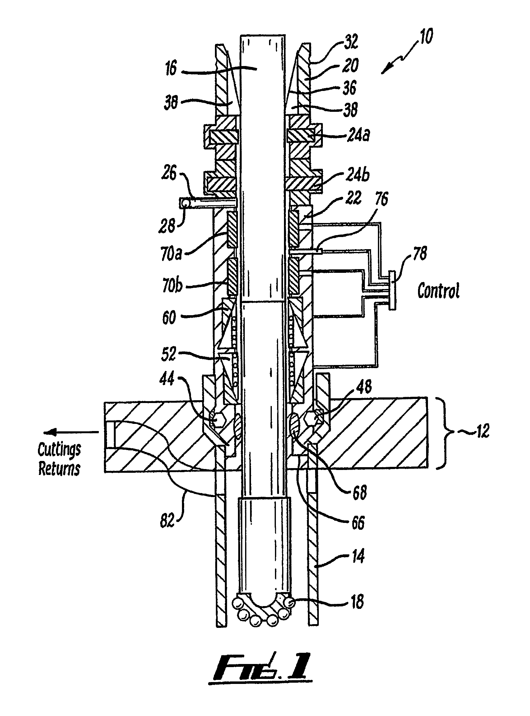
[0080]Reference is initially made to FIG. 1 of the drawings which illustrates a shut off device, generally indicated by reference numeral 10, for use in drilling a subsea well according to an embodiment of the present invention. The device 10 is shown together with a template 12, casing section 14 and a casing string 16 complete with drillshoe 18.

[0081]The shut off device 10 comprises upper 20 and lower 22 housings. The upper housing 20 comprises a dual set of 13⅝″ shear rams 24a,b. A side outlet 26 with a non-return valve 28 provides the means of connecting a kill line with an ROV (Remotely Operated Vehicle) as is known in the art. At the top 30 of the device 10 is a 13⅝″ re-entry hub 34 with the machined profile 32 of an industry standard external wellhead connector. Internally, a bellmouth 36 fabricated from composite material, in the form of a sleeve 38, provides a means of distributing the bending loads on the 7⅝″ casing 16 located therethrough.

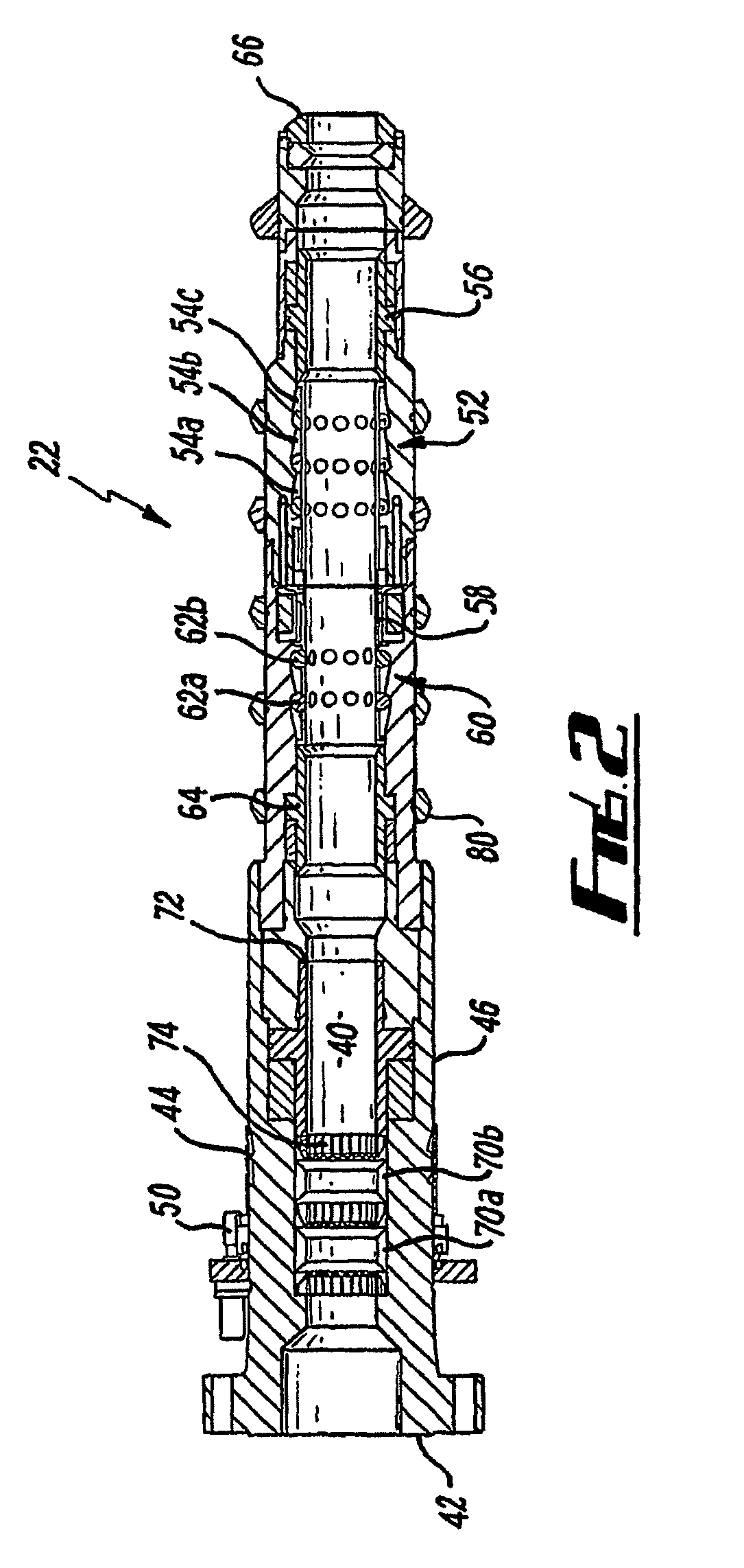
[0082]The lower housing 22 is bol...


PUM

PropertyMeasurementUnit
depthaaaaaaaaaa
pressureaaaaaaaaaa
pressureaaaaaaaaaa

Abstract

A subsea cutting device for a subsea blow-out preventer or wellhead comprises a tubular body having an axial throughbore, and configured to be fitted to a casing string, the cutting device further comprising a shearing mechanism in the form of a radial cutting system rotatably mounted within a pressure-containing housing, and comprising a plurality of movable cutters arranged around the throughbore and configured for deployment during rotation successively inwards. The cutting device is useful in a subsea shut off device which is latched to a template at surface and run to the sea floor on a casing string which is drilled into place and converted into a riser on a single trip. For the event when emergency disconnection is required, the device may be used to cut the casing and seal in the well. The system then allows a conventional subsea reconnection of the riser.

Description

CROSS-REFERENCE TO RELATED APPLICATIONS[0001]This is a Continuation-In-Part of application Ser. No. 11 / 658,359 (allowed) filed Jan. 23, 2007, which is a National Stage 371 Application of PCT / GB05 / 02885, filed Jul. 25, 2005. The entire disclosure(s) of the prior application(s), application Ser. No. 11 / 658,359 and PCT / GB05 / 02885 are hereby incorporated by reference.BACKGROUND OF THE INVENTION[0002]The present invention relates to subsea drilling of oil and gas wells and in particular, though not exclusively, to apparatus and method for a one trip deployment and drilling system to rapidly create exploration wells.[0003]Current practice in subsea drilling is to firstly establish a well by drilling a surface hole at the sea floor. Conductor casing is cemented at the top of the well upon which is located a subsea wellhead. Thereafter a Subsea Blowout Preventer Stack (BOP) is run and latched to the wellhead. Subsequent casing strings are then suspended in the wellhead.[0004]In many explora...

Claims


Application Information

Patent Timeline
Patent Type & Authority Patents(United States)
IPC IPC(8): E21B29/12
CPCE21B7/12E21B29/007E21B33/035E21B33/064E21B41/08
Inventor BAMFORD, ANTHONY S.
Owner QUANTUM LEAP TECH
Why Eureka
Try Eureka