Joint reconstruction planning using model data

a model data and reconstruction planning technology, applied in the field of joint reconstruction planning, can solve the problems of requiring a relatively long time for corresponding planning steps and computationally complex segments, and achieve the effects of avoiding elaborate and lengthy image processing operations, avoiding large expense, and sufficient reconstruction accuracy

Active Publication Date: 2013-11-26
SMITH & NEPHEW ASIA PACIFIC PTE LTD +2
View PDF7 Cites 9 Cited by
  • Summary
  • Abstract
  • Description
  • Claims
  • Application Information

AI Technical Summary

Benefits of technology

[0004]It is the object of the present invention to enable joint reconstruction planning which enables a sufficiently accurate reconstruction at little expense. The intention is in particular to avoid elaborate and lengthy image processing operations, in order to enable planning to be more flexibly used.
[0006]In other words, the present invention uses model data which is suitable for the upcoming bone reconstruction, in order to be able to deduce the abrasion or resection regions by processing such model information. Such model data, which can be model image data, can easily be processed and linked to the patient data set, in particular an image data set, and this also leads to quick results, in particular without the content of a patient image data set having to be elaborately analyzed. For in such analyses, the properties of the elements to be imaged, their identity and their delineation with respect to other elements are deduced from the image material; this process is called segmentation. Segmentation is computationally very elaborate, and the corresponding planning steps therefore take a relatively long time. If segmentation steps can be omitted with the aid of the model data, this enables planning to be more flexibly used and also to be adapted and changed. It is also in particular possible to plan intra-operatively using intra-operative image recordings (CT, MR). Another advantage of eliminating segmentation is that segmentation is often very difficult when image data sets of joint environments are produced. Usually, MR (magnetic resonance tomography) images are produced, because soft tissue defects play a major role in the ailments in question. However, it is very difficult to clearly segment bone structures in MR data, and for this reason too, the use in accordance with the invention of reconstruction-type model data for determining the resection auxiliary regions and ultimately the resection regions themselves is highly advantageous with respect to the prior art.

Problems solved by technology

Segmentation is computationally very elaborate, and the corresponding planning steps therefore take a relatively long time.

Method used


Image

  • Joint reconstruction planning using model data
  • Joint reconstruction planning using model data

Examples


Embodiment Construction

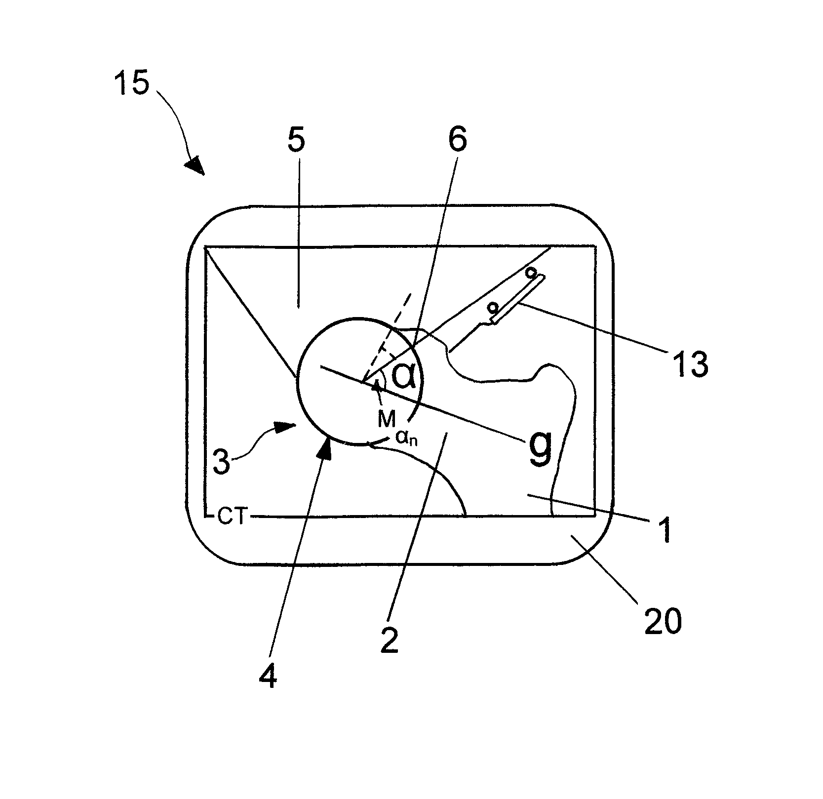
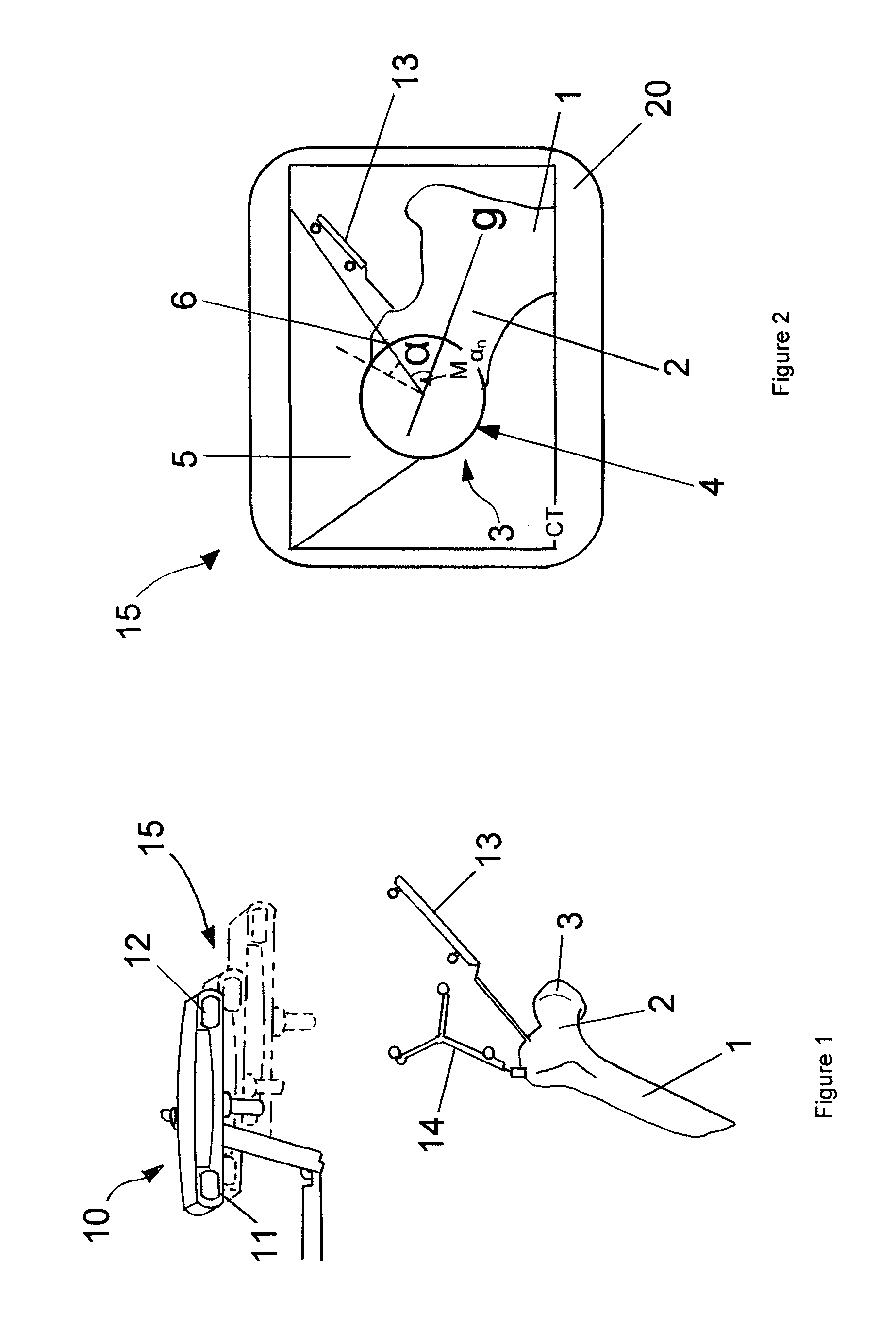
[0027]FIG. 1 schematically shows how an upper part of a femoral bone can be positionally located and tracked and / or registered with the aid of a medical tracking system 10. The tracking system 10 comprises two cameras 11 and 12 which can track the position of specific markers. Such markers are for example situated on the reference star 14 or on the pointer 13, which are shown in the lower part together with the image of the femoral bone 1, on which the femoral neck 2 and femoral head 3 can be seen.

[0028]The reference star 14 is fixedly connected to the femur 1. Because an image data set of the femur 1 has been produced beforehand, it is then possible to positionally assign this image data set to the femoral bone 1 via the reference star 14, i.e. to register the femoral bone. Therefore, the location of specific reference coordinates is then known, and direction information is also available, for example via the location of the femoral axis, the neck axis or the centre point of the he...


PUM


Abstract

The invention relates to a computer-assisted planning method for reconstructing changes in shape on joint bones, comprising the following steps:a three-dimensional patient data set is acquired;reconstruction-type model data is assigned to the patient data set;resection auxiliary regions are determined by means of the model data; andthe resection auxiliary regions are visually output and / or visualized together with the patient data set.

Description

RELATED APPLICATION DATA[0001]This application claims the priority of U.S. Provisional Application No. 61 / 056,882, filed on May 29, 2008, which is hereby incorporated in its entirety by reference.FIELD OF THE INVENTION[0002]The invention relates to the field of joint reconstruction planning; in particular, it relates to a computer-assisted planning method for reconstructing changes in shape on joint bones.BACKGROUND OF THE INVENTION[0003]Changes in the shape of joint bones are a possible cause of arthritic joint ailments. For example, bone anomalies can arise in the region of the hip joint which lead to bone collisions in the region of the joint when the leg is moved and—in particular over a longer period—cause attrition. In order to prepare reconstruction treatments, i.e. treatments which restore a suitable shape of the bone, planning is necessary which can be performed with computer assistance. The reshaping of the femoral head, and sometimes of the rim of the joint cavity, is pla...

Claims


Application Information

Patent Timeline
Patent Type & Authority Patents(United States)
IPC IPC(8): G06K9/18G06V30/224
CPCA61B19/50A61B19/5244A61B2019/505A61B2019/507A61B2019/5255A61B2019/5268A61F2002/4633A61B2034/2055A61B2034/2068A61B34/20A61B34/10A61B2034/105A61B2034/107
Inventor HAIMERL, MARTINSCHUBERT, MARIO
Owner SMITH & NEPHEW ASIA PACIFIC PTE LTD
Why Eureka
Try Eureka