Method and apparatus for tuning a communication device

a communication device and tuning technology, applied in the field of communication systems, can solve the problems of affecting the performance of antennas, and compromising the performance of antenna designers in some frequency bands

Active Publication Date: 2013-11-26
NXP USA INC
View PDF342 Cites 95 Cited by
  • Summary
  • Abstract
  • Description
  • Claims
  • Application Information

AI Technical Summary

Problems solved by technology

Due to size constraints, and aesthetic design reasons, the antenna designer is forced to compromise the performance in some of the frequency bands.
The antenna will not radiate efficiently at all frequencies due to the nature of the design, and the power transfer between the antenna, the power amplifier, and the receiver in the radio will vary significantly.
Additionally, an antenna's performance is impacted by its operating environment.
For example, multiple use cases exist for radio handsets, which include such conditions as the placement of the handset's antenna next to a user's head, or in the user's pocket or the covering of an antenna with a hand, can significantly impair wireless device efficiency.
Further, many existing radios use a simple circuit composed of fixed value components that are aimed at improving the power transfer from power amplifier to antenna, or from the antenna to the receiver, but since the components used are fixed in value there is always a compromise when attempting to cover multiple frequency bands and multiple use cases.
Some detectors, such as a diode detector or a logarithmic amplifier, may not typically be adequate to detect such levels.
An RSSI measurement can be very noisy and unstable due to highly variable impairments in the propagation channel, such as fading.
However, the amount of averaging necessary could make such a measurement prohibitively slow and not suitable as feedback for closed loop antenna tuning.
A complication with using the transmit signal for tuning can be that it is at a different frequency than the receive signal and the objective of the tunable match in the diversity path is to adjust performance at the receive frequency.
This may prevent the use of an algorithm that simply targets a specific Tx signal level.
The unwanted frequency may be a harmonic or an interferer.
In a multiple antenna system, simply maximizing the over the air efficiency of all the antennas may not accomplish the best overall performance of the communication system.

Method used


Image

  • Method and apparatus for tuning a communication device
  • Method and apparatus for tuning a communication device
  • Method and apparatus for tuning a communication device

Examples


Embodiment Construction

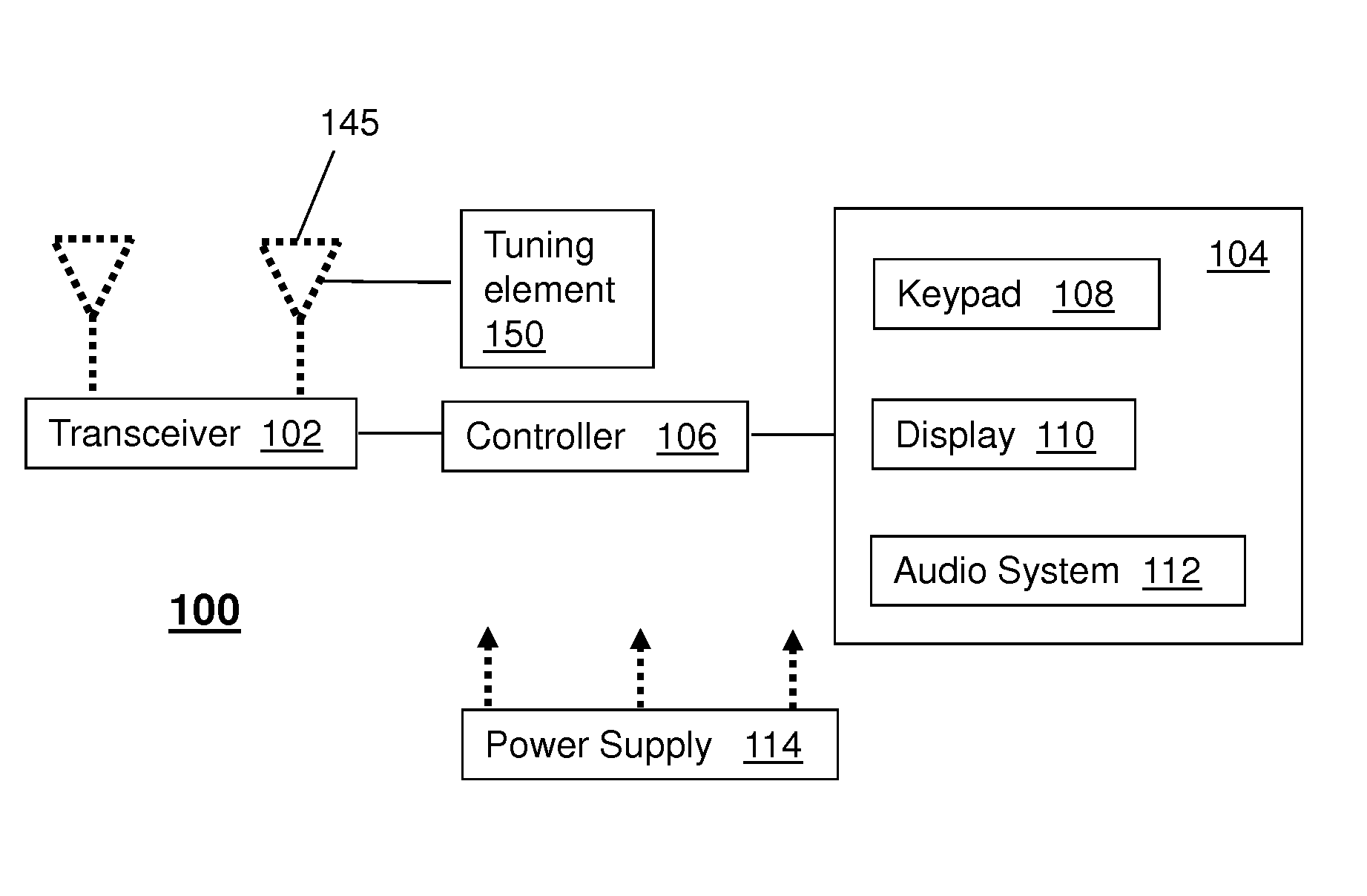
[0015]One or more of the exemplary embodiments described herein can have an antenna with a tunable element attached to the radiating elements of the antenna. The tunable element can be of various types, such as a Passive Tunable Integrated Circuit (PTIC) having one or more electrically tunable capacitors.

[0016]In one embodiment, the antenna can be directly tuned over frequency, moving the resonant frequency of the radiating element. By doing so, the magnitude of the VSWR that the antenna presents to the transceiver, can be adjusted, and can be kept within a range that is easier to match to the transceiver.

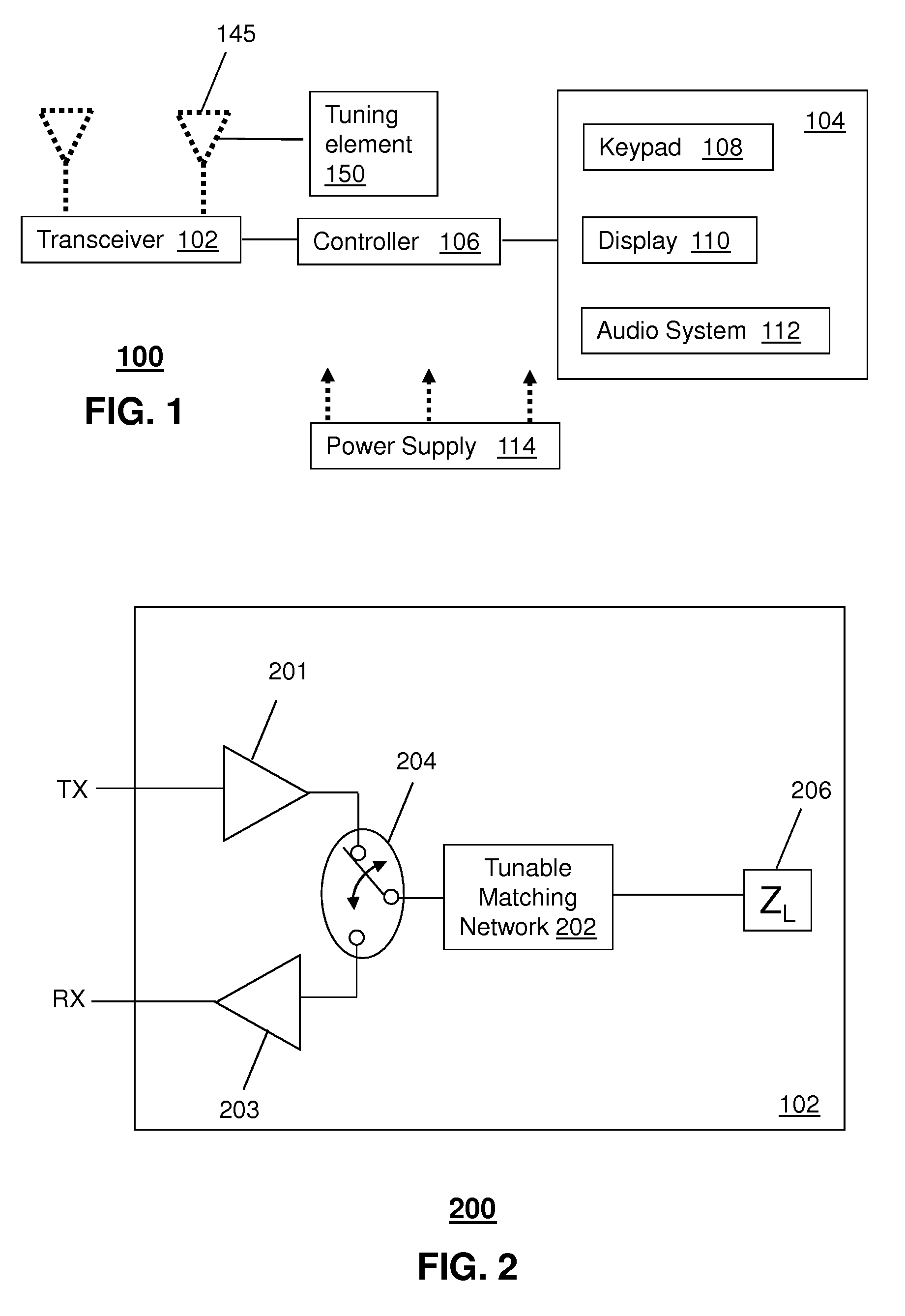
[0017]In another embodiment, on-antenna tuning can be combined with a tunable matching network such as positioned at a feed point of the antenna to achieve greater gains in total antenna efficiency as compared with utilizing either of these tuning methods separately.

[0018]In one embodiment, the tunable element on the antenna can be tuned using an open loop methodology, such as tuni...


PUM


Abstract

A system that incorporates teachings of the present disclosure may include, for example, a tuning system for a communication device having an antenna, where the tuning system includes at least one first tunable element connected with at least one radiating element of the antenna for tuning the antenna where the adjusting of the at least one first tunable element is based on at least one of a use case associated with the communication device and location information associated with the communication device, and a matching network having at least one second tunable element coupled at a feed point of the antenna, wherein the matching network receives control signals for adjusting the at least one second tunable element to tune the matching network. Additional embodiments are disclosed.

Description

CROSS-REFERENCE TO RELATED APPLICATIONS[0001]The present application is related to U.S. application Ser. No. 13 / 108,589 filed May 16, 2011, and which is titled “Method and Apparatus For Tuning A Communication Device”, the disclosure of which is hereby incorporated by reference.FIELD OF THE DISCLOSURE[0002]The present disclosure relates generally to communication systems, and more specifically to a method and apparatus for tuning a communication device.BACKGROUND[0003]Existing multi-frequency wireless devices (e.g., radios) use an antenna structure that attempts to radiate at optimum efficiency over the entire frequency range of operation, but can really only do so over a subset of the frequencies. Due to size constraints, and aesthetic design reasons, the antenna designer is forced to compromise the performance in some of the frequency bands. An example of such a wireless device could be a mobile telephone that operates over a range of different frequencies, such as 800 MHz to 2200 ...

Claims


Application Information

Patent Timeline
Patent Type & Authority Patents(United States)
IPC IPC(8): H04B1/40
CPCH04B1/0458H04B1/18H01Q1/50H01Q5/50H04B1/48
Inventor GREENE, MATTHEW R.MANSSEN, KEITH R.MENDOLIA, GREGORY
Owner NXP USA INC
Why Eureka
Try Eureka