Frontlight unit for enhancing illumination of a reflective display

a technology for frontlight units and reflective displays, applied in lighting and heating equipment, instruments, transportation and packaging, etc., can solve the problems of insufficient brightness and contrast, inefficient use of light sources, complex structure, etc., and achieve uniform illumination

Inactive Publication Date: 2013-12-03
VELIKOV LEONID MR +1
View PDF23 Cites 39 Cited by
  • Summary
  • Abstract
  • Description
  • Claims
  • Application Information

AI Technical Summary

Benefits of technology

[0015]The present invention relates to frontlight units for reflective displays having pixels arranged in a matrix pattern and is aimed at improving image quality, i.e., image brightness and contrast. Such displays are used, e.g., in electronic calculators, electronic labels, so-called electronic paper, or the like, and are also aimed at improving efficiency of light-source energy consumption.
[0021]Thus, the same objective as that claimed in U.S. patent application Ser. No. 13 / 373,434 is achieved but without the use of second light-redirecting means, i.e., reflective mirrors. As a result, the structure is simplified, thus reducing manufacturing cost of the frontlight unit for reflective displays as a whole.
[0023]According to another aspect of the invention, the reflective-display frontlight illumination system of the above-described type may have holograms that are further provided with light-focusing features so that light beam focus points can be located above and below the holograms in the upper and lower parts of the cladding, respectively, i.e., above or below the core. Actual positions of such focus points are determined by hologram pattern topology. This makes it possible to form converging and / or diverging light beams, and this property, in turn, can contribute to uniformity of illumination.

Problems solved by technology

Common drawbacks of existing frontlight display illumination systems are inefficient use of light source, insufficient brightness and contrast, and complexity of structure.
However, the reflective mirrors occupy up to 10% of the surface area of the display, thus blocking a portion of image-carrying light.

Method used


Image

  • Frontlight unit for enhancing illumination of a reflective display
  • Frontlight unit for enhancing illumination of a reflective display
  • Frontlight unit for enhancing illumination of a reflective display

Examples


Embodiment Construction

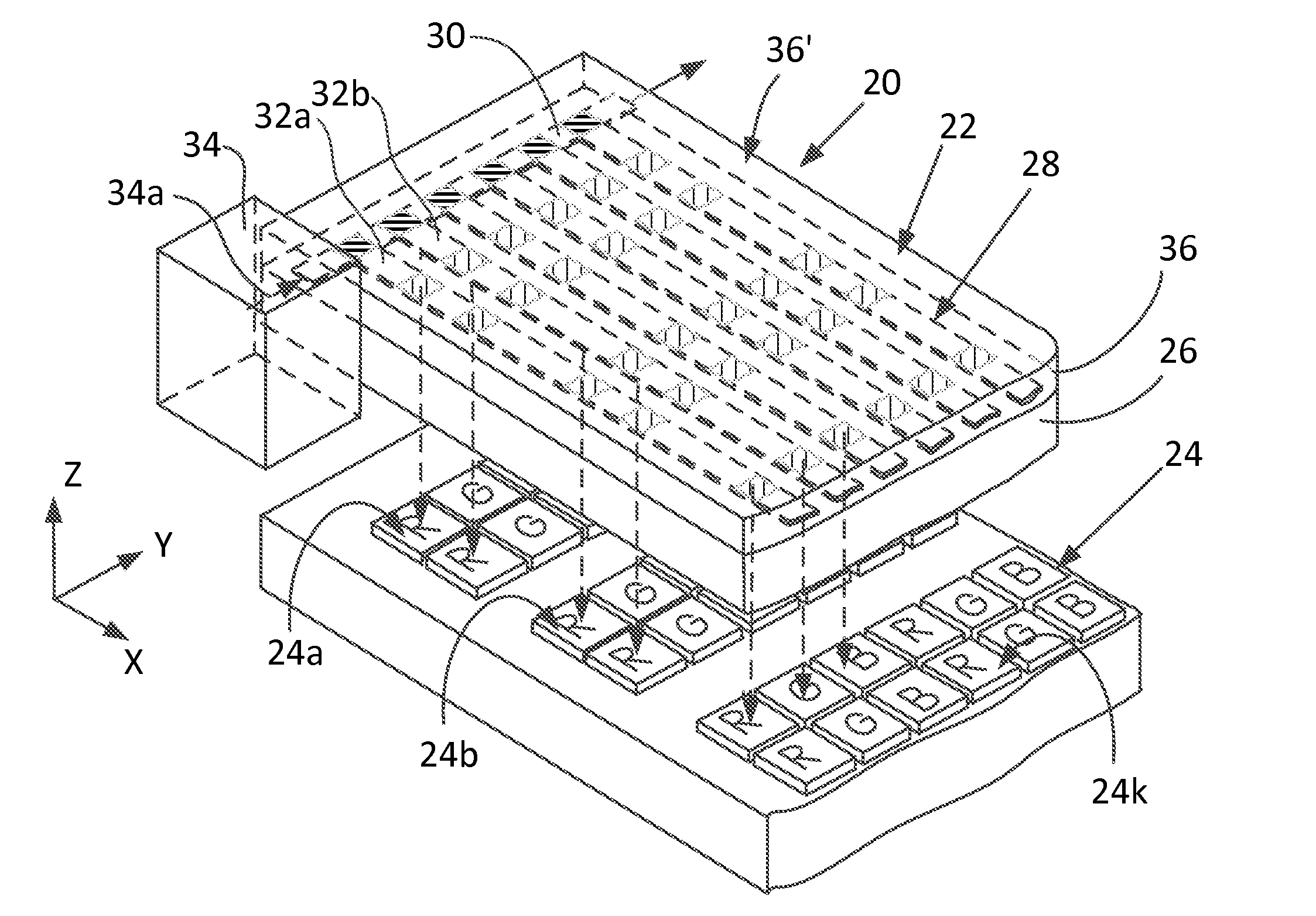
[0029]The present invention relates to a frontlight illumination system for reflective displays having pixels arranged in a matrix pattern and is aimed at improving image quality, i.e., brightness and contrast of images reproduced for displays used in ambient light. Displays of this type are employed, e.g., in electronic calculators, electronic labels, so-called electronic paper, etc., and are also aimed at decreasing energy consumption of the light source.

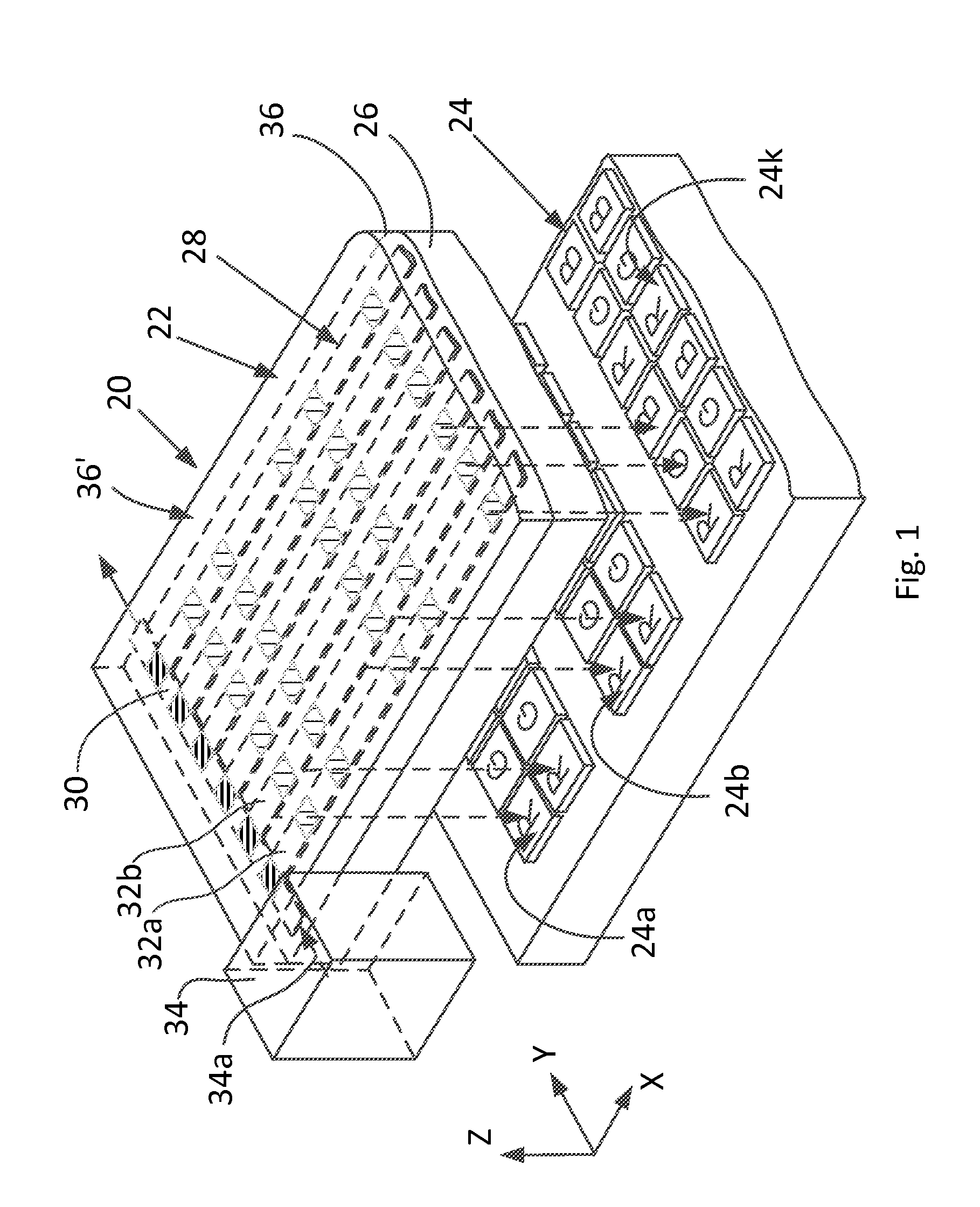
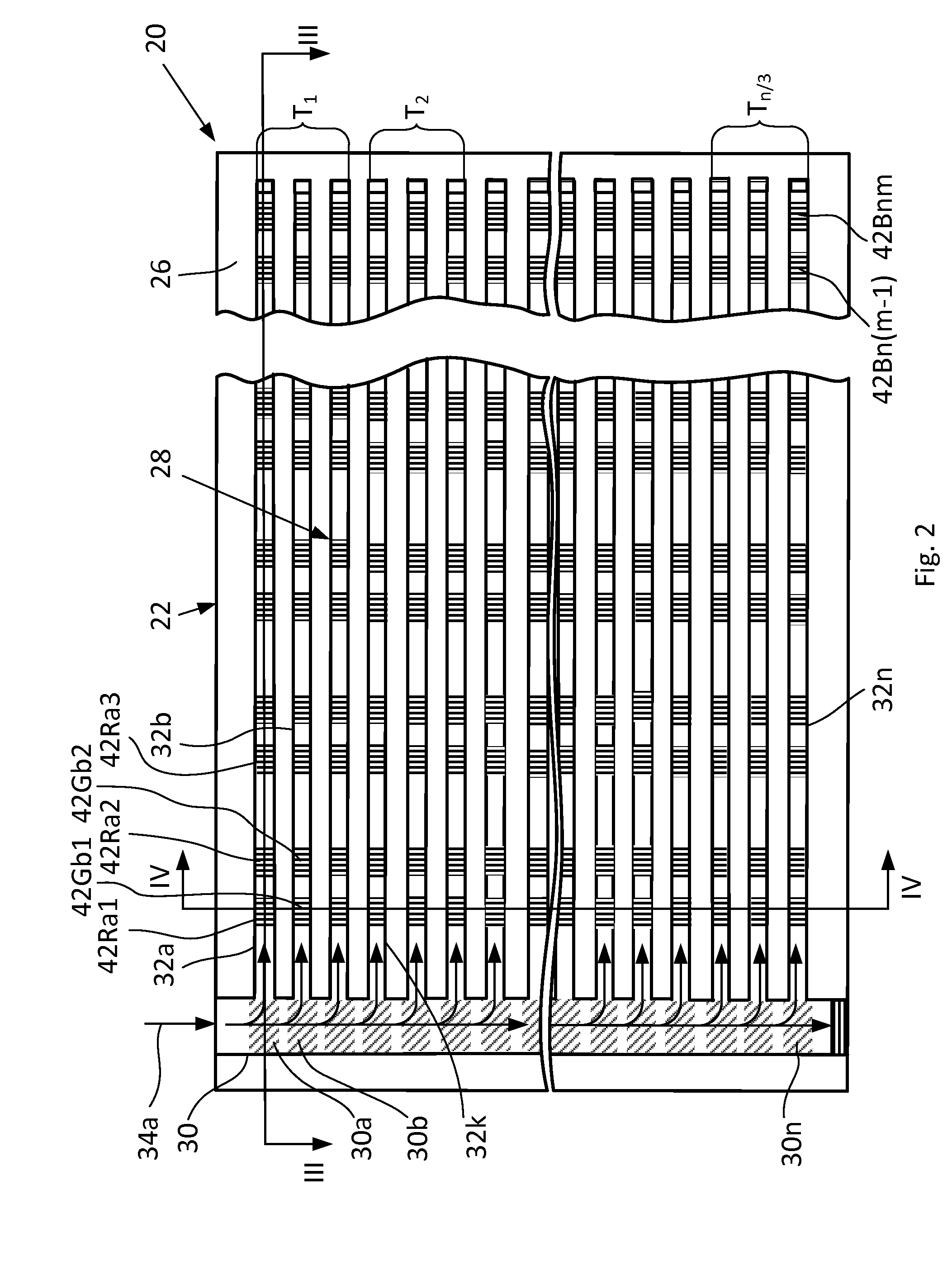
[0030]The invention will now be described in detail with reference to the accompanying drawings, where FIG. 1 is a simplified three-dimensional exploded view of the frontlight illumination system for a reflective display in accordance with one aspect of the invention, FIG. 2 is a top view of a planar ridge waveguide net with binary holograms used in the frontlight illumination system of the invention, FIG. 3 is a sectional view along the line III-III in FIG. 2, and FIG. 4 is a sectional view along the line IV-IV in FIG. 2.

[0031]As...


PUM


Abstract

The frontlight illumination system is intended for enhancing illumination of a reflective display having pixels arranged in a matrix pattern and using monochromatic laser lights as light sources. The unit contains a network of light-distributing planar ridge waveguides with holograms arranged in a matrix pattern that corresponds to the matrix pattern of the reflective display. The light-distributing holograms of the system are formed on opposite sides of each core of respective light-distributing planar ridge waveguides. Neighboring holograms located on opposite sides of the core are combined into pairs and are arranged on each core in positions at which they interact with a predetermined phase shift that doubles the intensity of light directed to the reflective display and extinguishes light directed to the external surface.

Description

FIELD OF THE INVENTION[0001]The present invention relates to a frontlight unit for reflective displays and is aimed at improving brightness of illumination and efficiency of light-source energy consumption. The invention may find use in displays of mobile devices having poor illumination conditions such as laptop computers, cell phones, iPads or tablets, so-called electronic paper, electronic calculators, electronic labels, or the like.BACKGROUND OF THE INVENTION[0002]A frontlight unit is a means for illuminating a display assembly, such as a liquid crystal display (LCD), an interferometric modulation display (IMOD), or a display that is viewed in ambient light. A provision of the frontlight unit improves performance of the display in poor lighting conditions. Frontlights are inferior to backlights and are usually used as an auxiliary feature.[0003]Generally, a display presents an image by absorbing some of the light passing through. When an electrical field is applied across the cr...

Claims


Application Information

Patent Timeline
Patent Type & Authority Patents(United States)
IPC IPC(8): F21V7/04
CPCG02B6/0035G02F2001/133616G02B6/0028G02F1/133616
Inventor YANKOV, VLADIMIRGOLTSOV, ALEXANDERIVONIN, IGORVELIKOV, LEONID
Owner VELIKOV LEONID MR
Why Eureka
Try Eureka