Steel wire hook

a wire hook and wire technology, applied in the direction of snap fasteners, buckles, mechanical devices, etc., can solve the problems of difficult to remove the hook without damage, serious damage to the sealing performance of the gasket, and the casing woven by the insulating materials, so as to prevent the operator from being injured.

Active Publication Date: 2013-12-10
WANG ZHANGJIAN
View PDF30 Cites 9 Cited by
  • Summary
  • Abstract
  • Description
  • Claims
  • Application Information

AI Technical Summary

Benefits of technology

[0010]An object of the present invention is to provide a steel wire hook which is capable of effectively preventing the operator from being injured by the tail end of the hook during the installation.
[0011]Another object of the present invention is to provide a steel wire hook which is capable of avoiding the invalidation of the sealing performance of the gasket caused by the adhesion of the tail end of the hook and the gasket.
[0016]Therefore, according to the steel wire hook of the present invention, the gasket can be firmly and effectively fastened to the installing surface by the flat base and the short leg tilted towards the top end portion. After installing the hook, the base of the hook and the framework of the gasket are at a same plane, and the end portion bent downwardly from the plane where the base of the hook is provided is inserted into a half of the thickness of the framework of the gasket, which not only effectively prevents the operator from being injured by the tail end of the hook during the installation, but also avoids the invalidation of the sealing performance of the gasket caused by the adhesion of the tail end of the hook and the gasket. The steel wire hook of the present invention effectively resolves the rotation of the head of the hook and the axial displacement between the inner and outer layers of the gasket. Furthermore, the steel wire hook of the present invention resolves the problem that the mechanical installation and manual installation can not be achieved at the same model hook.

Problems solved by technology

However, after installing the hook into the gasket, it is difficult to take off the hook without any damage to the gasket.
If the hook is forcibly taken off, the casing woven by the insulating materials and provided outside the gasket will be damaged, and the sealing performance of the gasket will be seriously affected.
During the weaving process, once a hook has the problem, the whole gasket is useless.
While installing the hook with the elliptic bottom and a short tail to the gasket, it is prone to adhere the tail to the exterior wall of the gasket, which causes the whole gasket to be depressed at a position where the hook is located, so that the sealing performance is affected.
The effect is fatal to seal the heat chamber of the heating device.
Also, due to the tail, while installing the gasket to the oven door, it is possible for the operator to be injured by the tilting tail.
Furthermore, it is difficult for the hook provided by this solution to be directly inserted into the gasket while weaving the gasket.
The head portion of the hook provided by this solution can rotate along the axis of the neck and the top portion after installing the hook into the gasket, which will bring great puzzle to the operator.
Also, in the solution, while the hook is installed to the installing plane, the tail end of the wire of the base is extruded to be tilted, so the probability that the operator is injured by the tail end of the wire of the base can not be avoided during the actual installation process.
In addition, in the solution, the base of the hook is circular, after the gasket is installed to the installation plane, the diameter of the base of the hook has a transverse extrusion to the gasket, so that the cross section of the gasket turns to be an irregular shape, which will directly result in the invalidation of the sealing of the heat chamber of the heating appliance.
The metallic wires of the base are close to each other and no gap among the wires is provided, so that while installing the hook to the gasket, the outer casing of the gasket is inclinable to be damaged, which will lead to the invalidation of the sealing performance of the heat chamber of the heating appliance.
In addition, the hand of the operator is easily injured by the tilted tail.

Method used


Image

  • Steel wire hook
  • Steel wire hook
  • Steel wire hook

Examples


Embodiment Construction

[0022]The present invention is further explained in detail with the accompanying drawings.

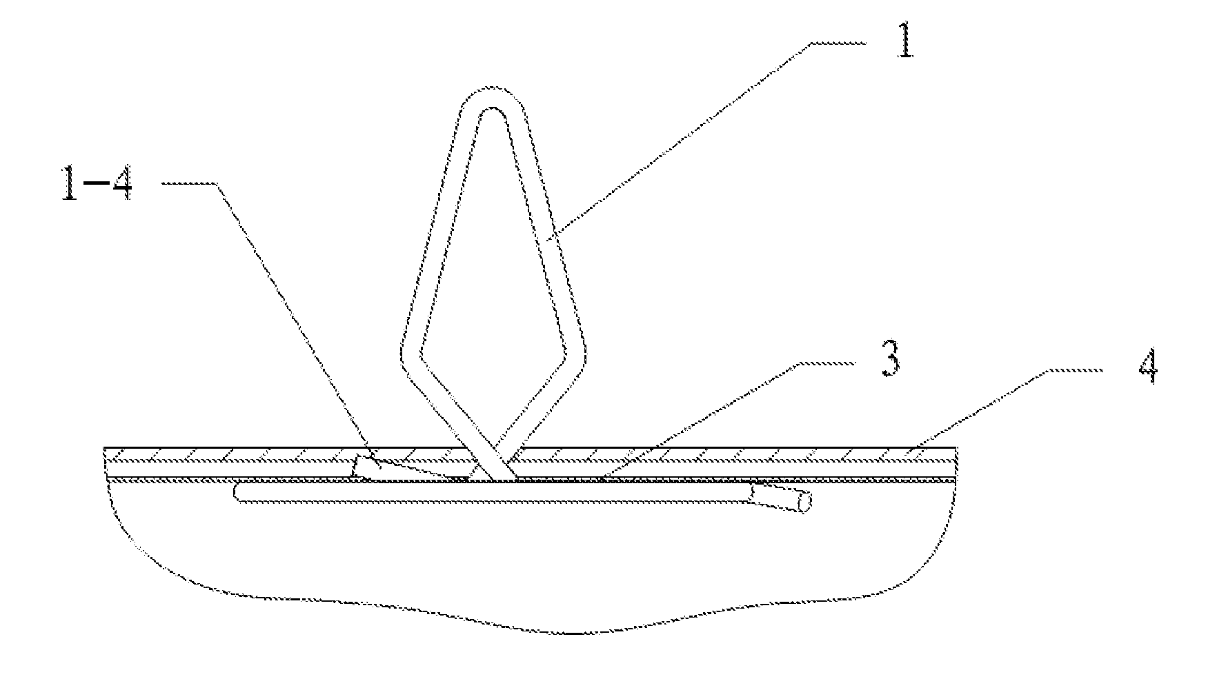
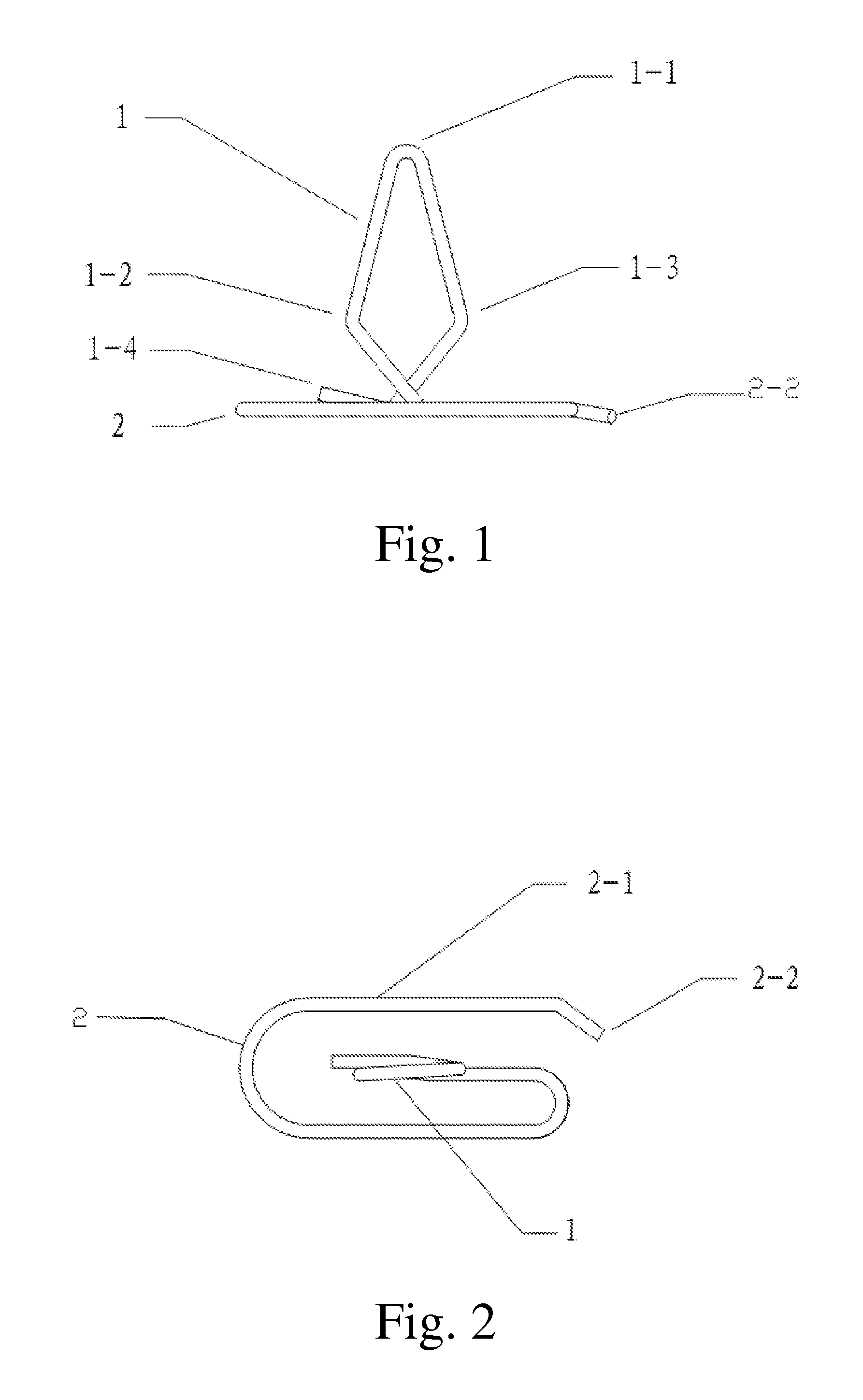
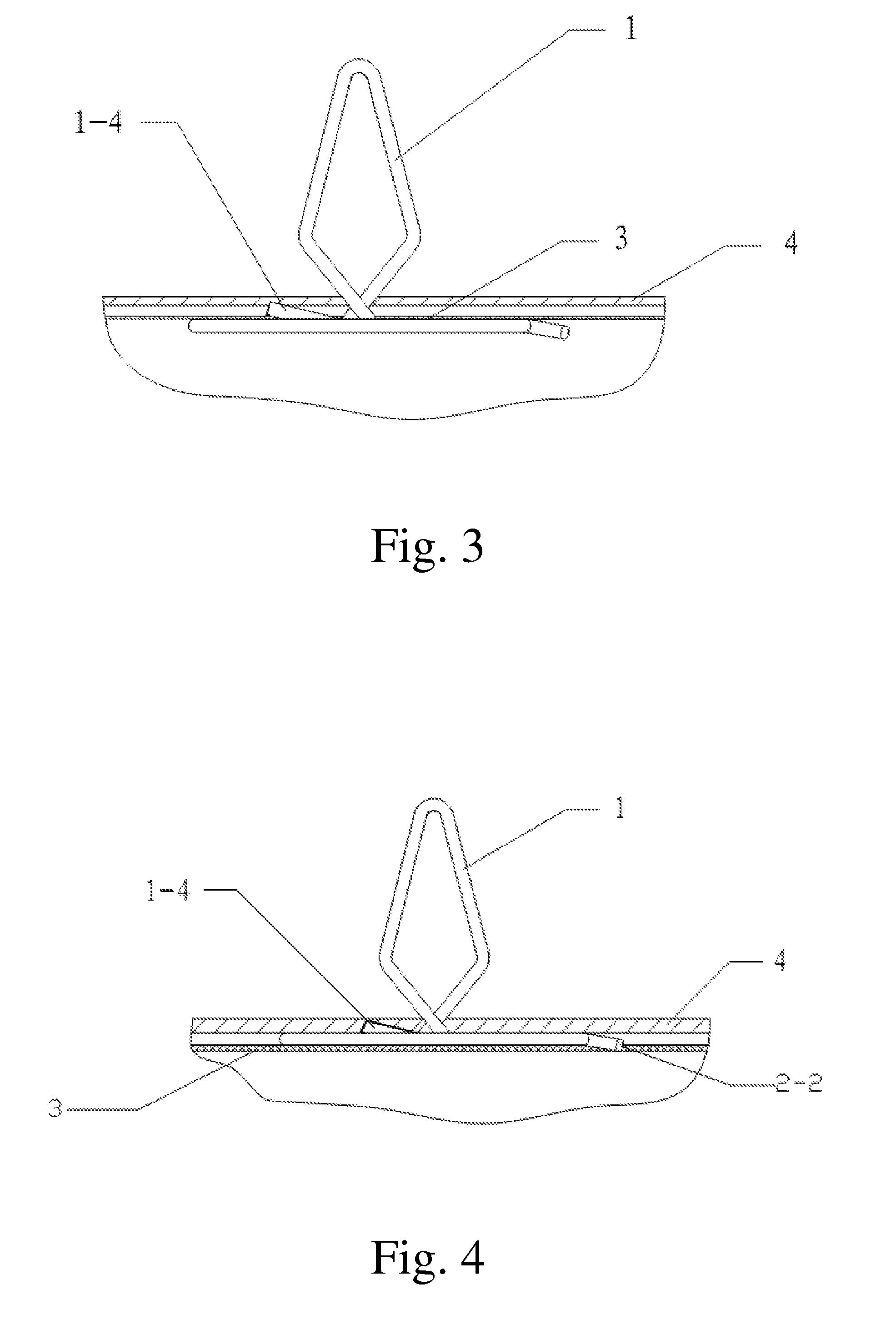
[0023]Referring to FIGS. 1 and 2 of the drawings, a steel wire hook according to a preferred embodiment of the present invention is illustrated, wherein the steel wire hook comprises a head 1 and a base 2 which are made of metallic wire. The head 1 is connected with the base 2. The plane where the head 1 is provided is perpendicular to the plane where the base 2 is provided. The head 1 comprises a circular-arc-shaped top end portion 1-1, a left shoulder 1-2, a right shoulder 1-3 and a short leg 1-4, wherein the left shoulder 1-2 and the right shoulder 1-3 are extended from the circular-arc-shaped top end portion 1-1 and are symmetrical to each other, the short leg 1-4 is provided at a lower end of the head 1, an angle is provided between the short leg 1-4 and the base 2, and the short leg 1-4 is tilted towards the circular-arc-shaped top end portion 1-1. The base 2 has an approximately oval-sha...


PUM


Abstract

A steel wire hook includes a head and a base which are made of metallic wire. The head is connected with the base. A plane where the head is provided is perpendicular to a plane where the base is provided. The head includes a circular-arc-shaped top end portion, a left shoulder, a right shoulder and a short leg. The left shoulder and the right shoulder are extended from the circular-arc-shaped top end portion and are symmetrical to each other. The short leg is provided at a lower end of the head and is tilted towards the circular-arc-shaped top end portion. An angle is provided between the short leg and the base. The base, having an approximately oval-shape and formed by coiling a metallic wire at a horizontal direction, includes a long leg which has a larger gap from the main body of the base.

Description

BACKGROUND OF THE PRESENT INVENTION[0001]1. Field of Invention[0002]The present invention relates to a steel wire hook for fastening a gasket, a sealing element or the like on an installation plane, which is generally used on the sealing element of the door of the oven, refrigerator, microwave oven and some heating equipments.[0003]2. Description of Related Arts[0004]There are the tubular gaskets at the peripheral edge of the door of the oven, refrigerator, microwave oven and some heating equipments. These gaskets mainly act as the sealing members, and also the other members. These gaskets consist of the framework which is woven by the metallic wire and has good flexibility and the outer casing which is woven by the insulating materials. It has been proved that this structure can be applied in the continuous high-temperature self-cleaning oven, and simultaneously, the gasket can provide good sealing performance in spite that the oven door is repeatedly switched-on / off for many years...

Claims


Application Information

Patent Timeline
Patent Type & Authority Patents(United States)
IPC IPC(8): F16B1/00
CPCF16B2/248F16B5/0642Y10T24/308Y10T24/44026Y10T24/44983
Inventor WANG, ZHANGJIAN
Owner WANG ZHANGJIAN
Why Eureka
Try Eureka