
Clamping apparatus for wood chipper

a technology of wood chipper and clamping apparatus, which is applied in the direction of cocoa, flat surfacing machine, solid separation, etc., can solve the problems of affecting the life of the knife and the quality of the product produced, the apparatus for securing the knives within the chipper is generally rather complex and expensive to build and maintain, and the removal of the knives from the machine for refurbishing or replacing is usually a time-consuming procedure, so as to achieve the effect of greatly reducing the effect of off-

Active Publication Date: 2013-12-10
CEM MACHINE
View PDF21 Cites 2 Cited by
  • Summary
  • Abstract
  • Description
  • Claims
  • Application Information

AI Technical Summary

Benefits of technology

The system effectively resists off-axis loads, enabling the use of smaller knives without compromising efficiency or product quality, simplifying knife handling and maintenance, and reducing the risk of knife damage and handling hazards.

Problems solved by technology

The knives that are typically used in these heavy duty machines are subjected to high impact loads which, if not effectively resisted can adversely affect the life of the knives and quality of the product produced in the machine depending upon various loading factors.
As a result, the apparatus for securing the knives within a chipper is generally rather complex and expensive to build and maintain.
Removal of the knives from the machine for refurbishing or replacing is usually a time consuming procedure.
In addition, handling the massive knives is a multi-worker task and can pose a danger to the workers and the knives if the knives are mishandled or dropped.
Systems employing much smaller knives meanwhile typically compromise the strength of the knives and the holding system resulting in a weaker overall clamping and holding system.
The clamping arrangement, however, is not as well suited to resist loads other than those running along these two primary axes or to couples arising from loads not being applied concentrically with the disc key supports or the holding bolts.
These off-axis loads and couples are generally concentrated along one edge section of the bolt heads, a condition referred to as “point loading” of the bolt head, which results in a reduction in the holding effectiveness of the clamp and clamping bolts.
When point loading occurs, the bolts or knife clamps can fatigue and fail giving rise to an unsafe situation of inadequately clamped knives and knives rapidly become dull or damaged and the quality of the chips produced being greatly reduced.

Method used


Image

  • Clamping apparatus for wood chipper
  • Clamping apparatus for wood chipper
  • Clamping apparatus for wood chipper

Examples


Embodiment Construction

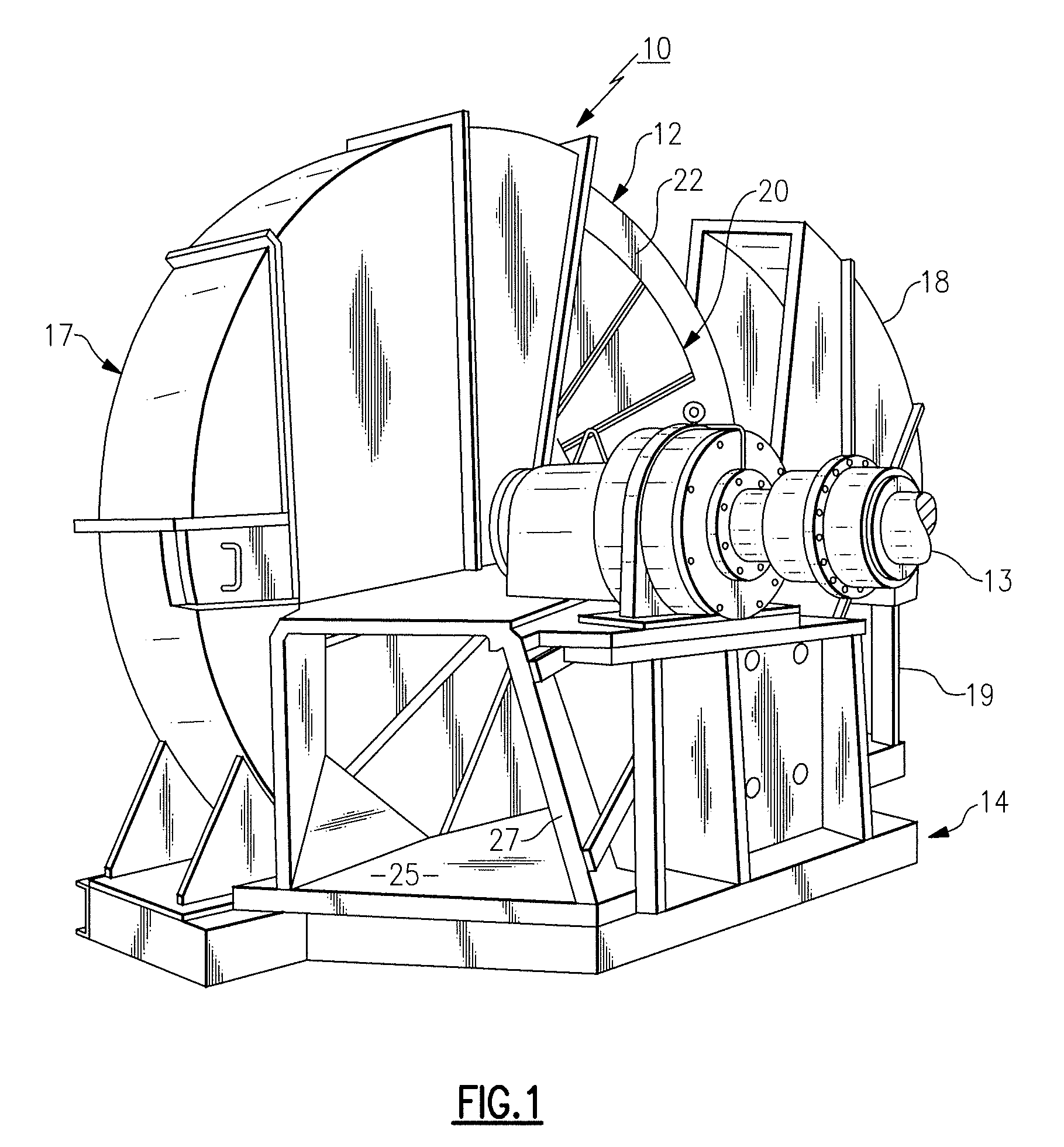
[0022]Referring initially to FIG. 1, there is illustrated a front perspective view of a heavy duty rotary disc wood chipper, generally referenced 10, that embodies the teachings of the present invention. The chipper is of a well known Heavy Duty design that includes a vertically disposed disc 12 that is mounted for rotation upon a horizontal drive shaft 13. The shaft is supported in bearing blocks that are mounted upon a stationary frame 14 along with a drive motor (not shown).

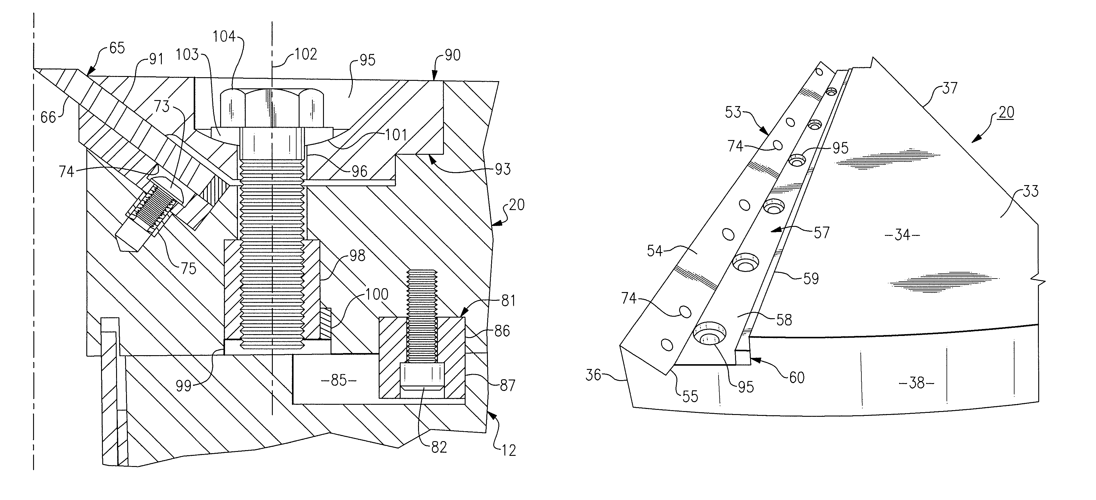
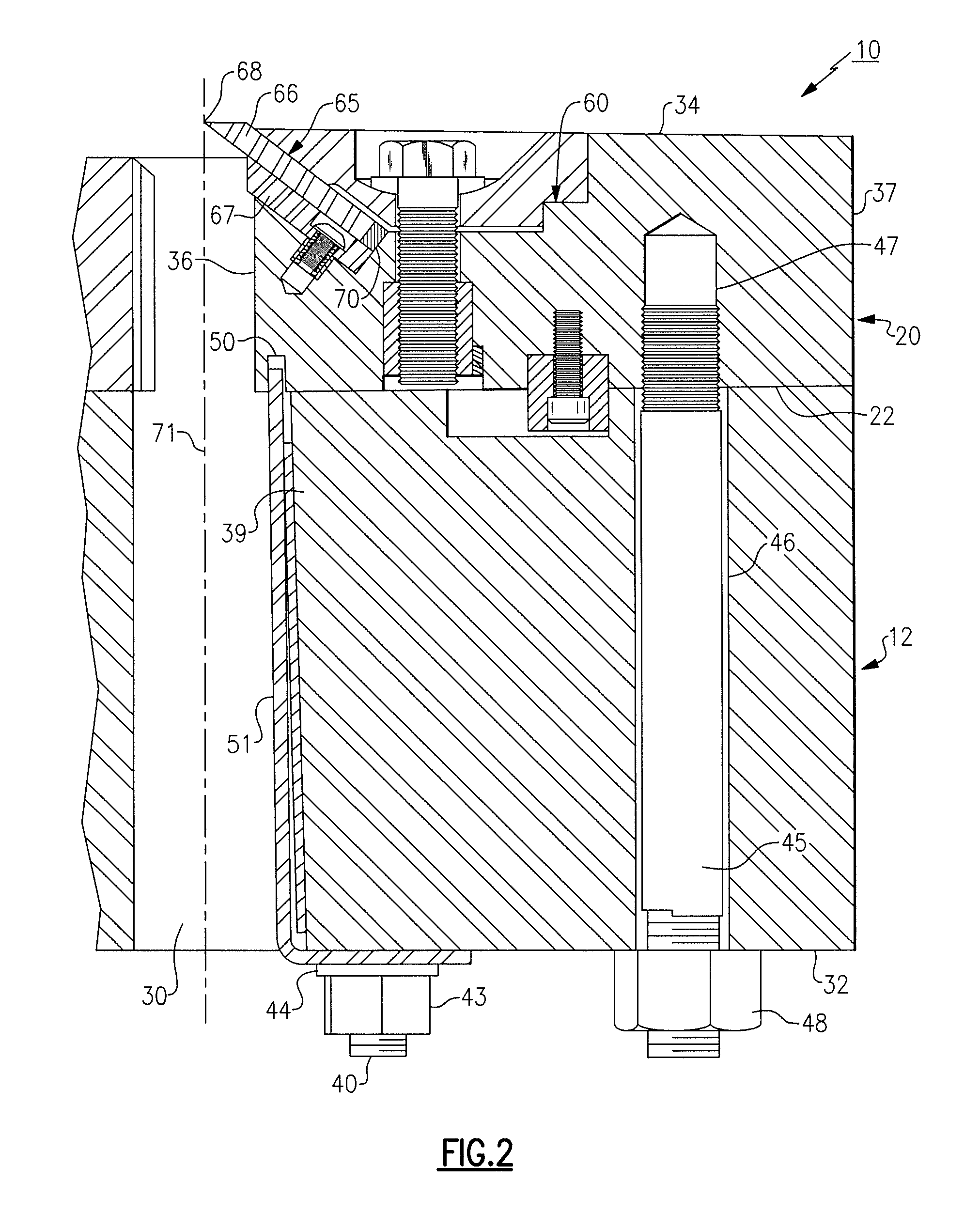
[0023]The disc 12 is enclosed within a protective housing, generally referenced 17, made up of a number of separtable sections. One of the sections 18 is shown moved back along a rail system 19 to permit clear access to the disc. A number of triangular shaped knife holders 20, sometimes referred to as segments, are secured to the front face of the disc. As will be described in greater detail below, each knife holder supports one or more chipper knives which are drawn through a stationary chipping station 25 as...


PUM


Abstract

A heavy duty rotary disc-type wood chipper containing a knife clamping system that conducts the impact and shearing loads acting upon the chipper knives along two primary axes which allows for more efficient dissipation of the impact loads and a reduction in the deleterious effects of off-axis loads resulting in the ability to use smaller holding bolts and smaller knives in the system without adversely effecting either the ability of the knives to stay fixed to the disc or the quality of chips produced.

Description

FIELD OF THE INVENTION[0001]This invention relates to a wood chipper and, more specifically, to a heavy duty rotary disc wood chipper, however this same concept can also be applied to clamping of knives mounted in drum chippers.BACKGROUND OF THE INVENTION[0002]Heavy duty wood chippers that are capable of producing large amounts of chips in a relatively short period of time typically employ a circular disc that is mounted for rotation upon a horizontally disposed drive shaft. A plurality of rectangular knives are radially extended upon the front face of the disc. Each knife is, in turn, aligned adjacent to a chip slots that passes through the disc between its front face and back face. Logs or similar work pieces are brought into contact with the front face of the rotating disc within a stationary work station where the moving knives act in association with a stationary bed knife to remove chips from the work pieces. The chips are conducted through the chip slots and exhausted from th...

Claims


Application Information

Patent Timeline
Patent Type & Authority Patents(United States)
IPC IPC(8): B02C7/00B02C17/02B27C1/00
CPCB02C18/08B02C2201/066B27L11/005
Inventor BOLIVER, SCOTT J.MCBRIDE, DANIEL
Owner CEM MACHINE
Learn More