Impeller which includes improved means of cooling

a technology of impeller and cooling means, applied in the field of impellers, can solve the problems of affecting the service life of the impeller, the method of cooling the impeller is sometimes used, and the impeller may be subjected to a radial thermal

Active Publication Date: 2013-12-10
SN DETUDE & DE CONSTR DE MOTEURS DAVIATION S N E C M A
View PDF8 Cites 11 Cited by
  • Summary
  • Abstract
  • Description
  • Claims
  • Application Information

AI Technical Summary

Benefits of technology

[0011]In particular it aims to reduce thermal gradients in gas turbine impeller disks such as in the low pressure turbines of aircraft turbine engines.
[0016]Because the crests of the teeth are the hottest parts of the disk in operation, the means of channelling allow optimum cooling of the disk and optimum reduction of the radial thermal gradient in this disk.
[0019]The sealing ring is used to block off the bottoms of the recesses and thus compel the flow of cooling air to pass radially towards the exterior up to the crests of the teeth in the disk.
[0024]Thus the side plate may be swept over and cooled by the flow of cooling air over its entire radial extent in order to achieve maximum reduction of the risks of deformation and of loss of efficiency of the side plate in operation.

Problems solved by technology

The temperature of the gases which flow in the turbines is in general high, in particular at the inlet to low pressure turbines fitted at the outlet of the combustion chamber in twin-shaft turbine engines, so that the disk of the impeller may be subjected to a radial thermal gradient which is detrimental to the service life of this disk.
This method of cooling the impeller disk is sometimes, however, shown to be insufficient, in particular when the temperature of the flow of gases driving the rotor reaches such a value that the thermal gradient resulting from this in the side plate causes it to deform in such a way that its gas-tightness, and therefore its capacity to cool the disk, is reduced.
Furthermore, the method of cooling described above does not provide cooling of the peripheral teeth of the disk, which are, however, the hottest part of the disk since they are very close to the flow of hot gases flowing in these turbines.
This method of cooling does not therefore allow the radial thermal gradient in the disks to be reduced in an optimum manner, and could even result in the thermal gradient between the crests of the teeth, which are heated by the hot gases which are flowing in the turbines, and the bases of the teeth, which are cooled by the flow of cooling air, becoming more marked.

Method used


Image

  • Impeller which includes improved means of cooling
  • Impeller which includes improved means of cooling
  • Impeller which includes improved means of cooling

Examples


Embodiment Construction

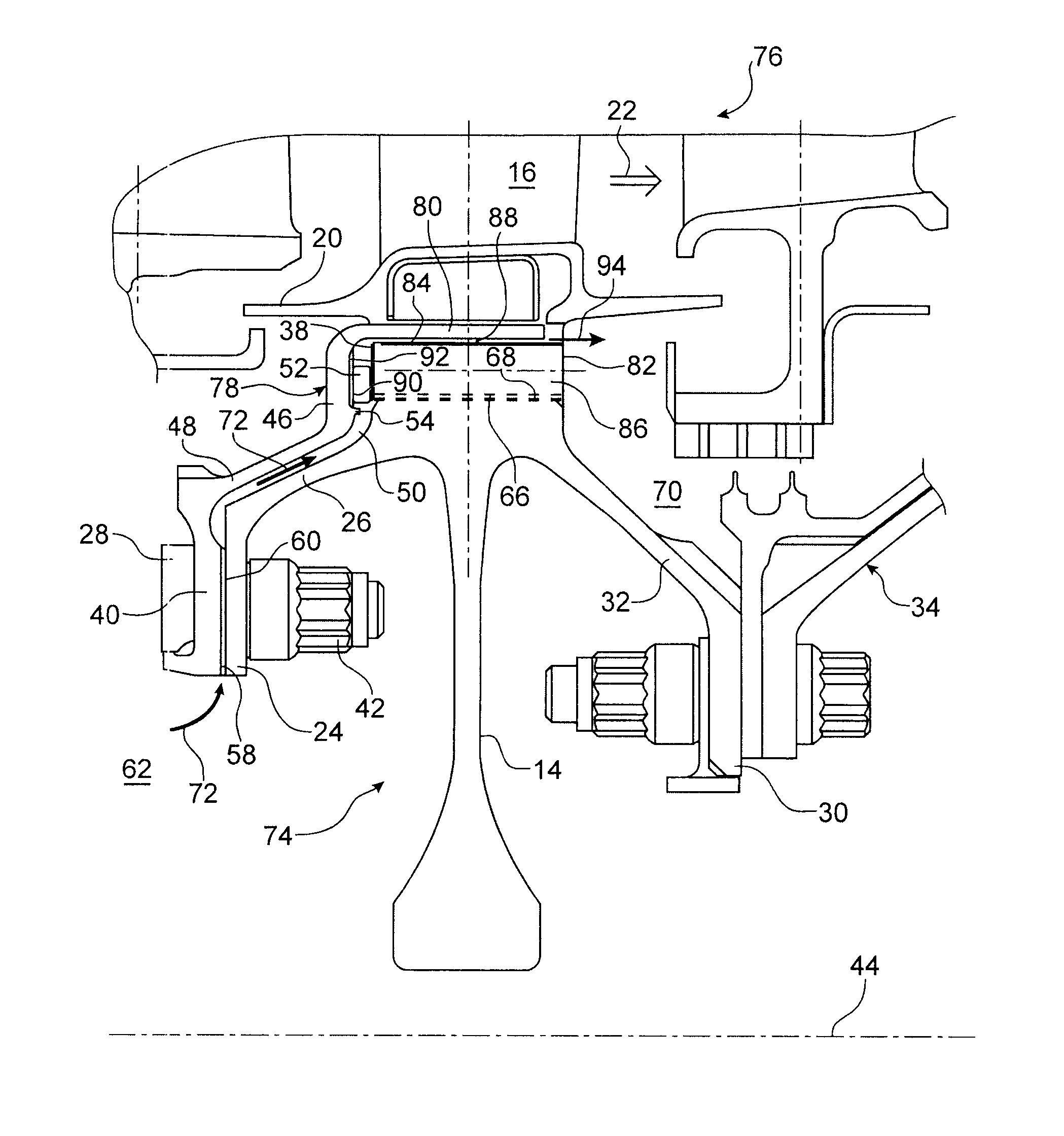
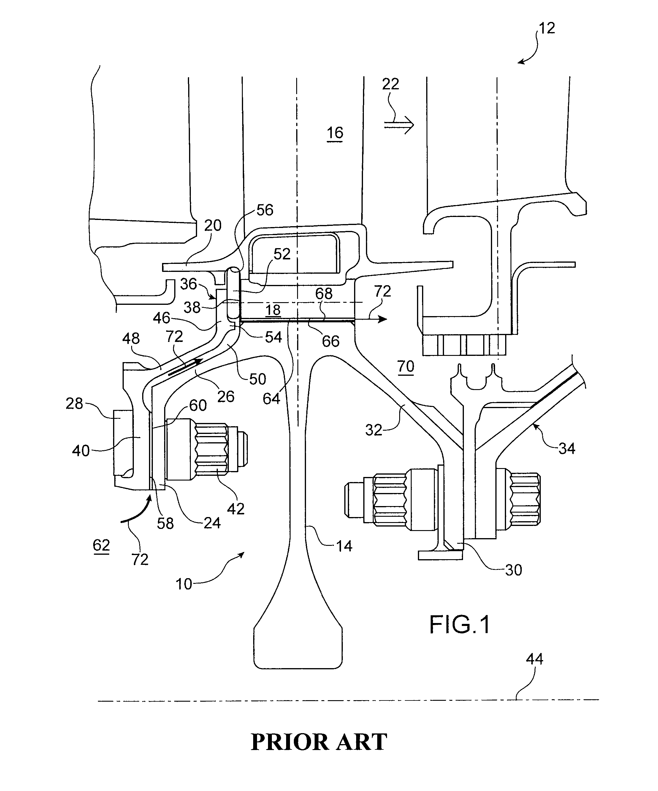
[0046]FIG. 1 represents an impeller 10 of a known type which forms the first stage of the rotor of a low pressure turbine 12 in a dual-flow, twin-shaft turbo-jet engine.

[0047]In a conventional manner, this low pressure turbine 12 is mounted at the outlet of a high pressure turbine, itself mounted at the outlet of an annular combustion chamber (not visible in FIG. 1).

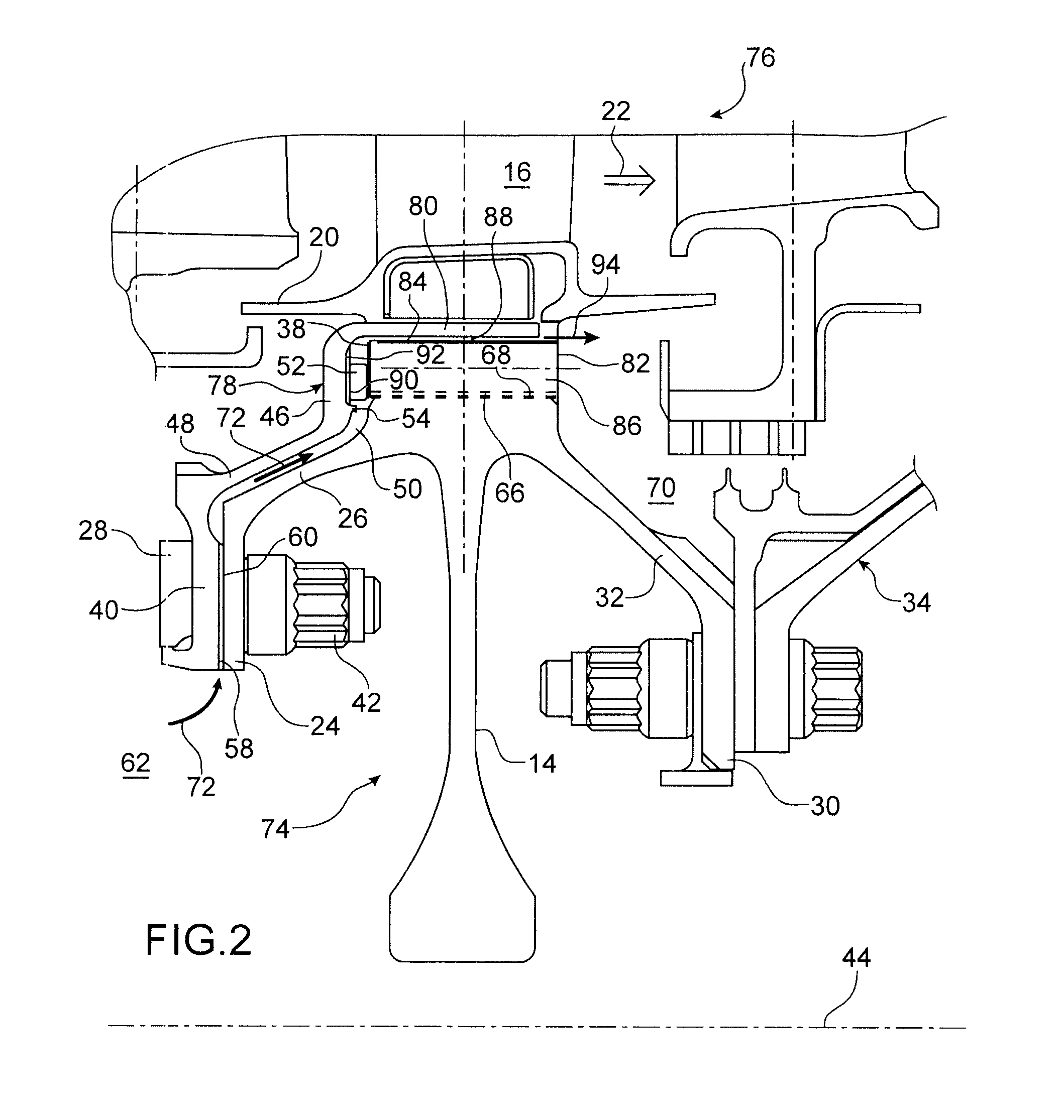
[0048]The impeller 10 includes a disk 14 equipped at its radially external periphery with teeth, which circumferentially demarcate axial recesses between each other, whose section is in the shape, for example, of a dovetail, and blades 16 each of which includes a foot 18 engaged and held with play in one of the aforementioned recesses.

[0049]Each blade 16 includes at its base a platform 20 intended in particular to guide, from upstream towards downstream in the turbine 12, that is, from the inlet towards the outlet of the turbine, a primary flow 22 of gases coming from the aforementioned combustion chamber.

[0050]The disk ...


PUM


Abstract

An impeller for a turbine engine which includes a disk provided with blade retention teeth, wherein associated with each tooth there is a mechanism for channelling a flow of cooling air which covers the crest of the tooth so that the latter is swept by the air flow. A turbine of turbine engine which includes an impeller of this type, and a turbine engine for aircraft which includes a turbine of this type.

Description

TECHNICAL FIELD[0001]The present invention relates to the field of impellers, in particular in turbines in turbine engines, such as aircraft turbo-jet engines.[0002]The invention relates more specifically to the cooling of the crests of the teeth of the disk of these impeller wheels, which are used to retain their blades.THE STATE OF THE PRIOR ART[0003]The rotor of gas turbines includes one or more impellers made to rotate by a gas flow, flowing from upstream to downstream within these turbines.[0004]Each impeller includes a disk fitted with peripheral teeth, which demarcate recesses between each other in which the tongues of the blades are held.[0005]The temperature of the gases which flow in the turbines is in general high, in particular at the inlet to low pressure turbines fitted at the outlet of the combustion chamber in twin-shaft turbine engines, so that the disk of the impeller may be subjected to a radial thermal gradient which is detrimental to the service life of this dis...

Claims


Application Information

Patent Timeline
Patent Type & Authority Patents(United States)
IPC IPC(8): F01D5/08
CPCF01D5/081F01D5/3015F01D11/006Y02T50/676F05D2260/20Y02T50/60
Inventor PHILIPPOT, VINCENT
Owner SN DETUDE & DE CONSTR DE MOTEURS DAVIATION S N E C M A
Why Eureka
Try Eureka