
Liquid supply device
a liquid supply device and liquid supply technology, applied in the direction of positive displacement liquid engine, piston pump, instrument, etc., can solve the problems of deterioration, deterioration, and deterioration of the life time so as to prevent elastic deformation, improve the durability of the liquid supply device, and improve the discharge accuracy of the pump
- Summary
- Abstract
- Description
- Claims
- Application Information
AI Technical Summary
Benefits of technology
Problems solved by technology
Method used
Image

Examples
Embodiment Construction
[0050]Embodiments according to the present invention will be detailed below based on the accompanying drawings. The same reference numerals are denoted to members common to the respective drawings.
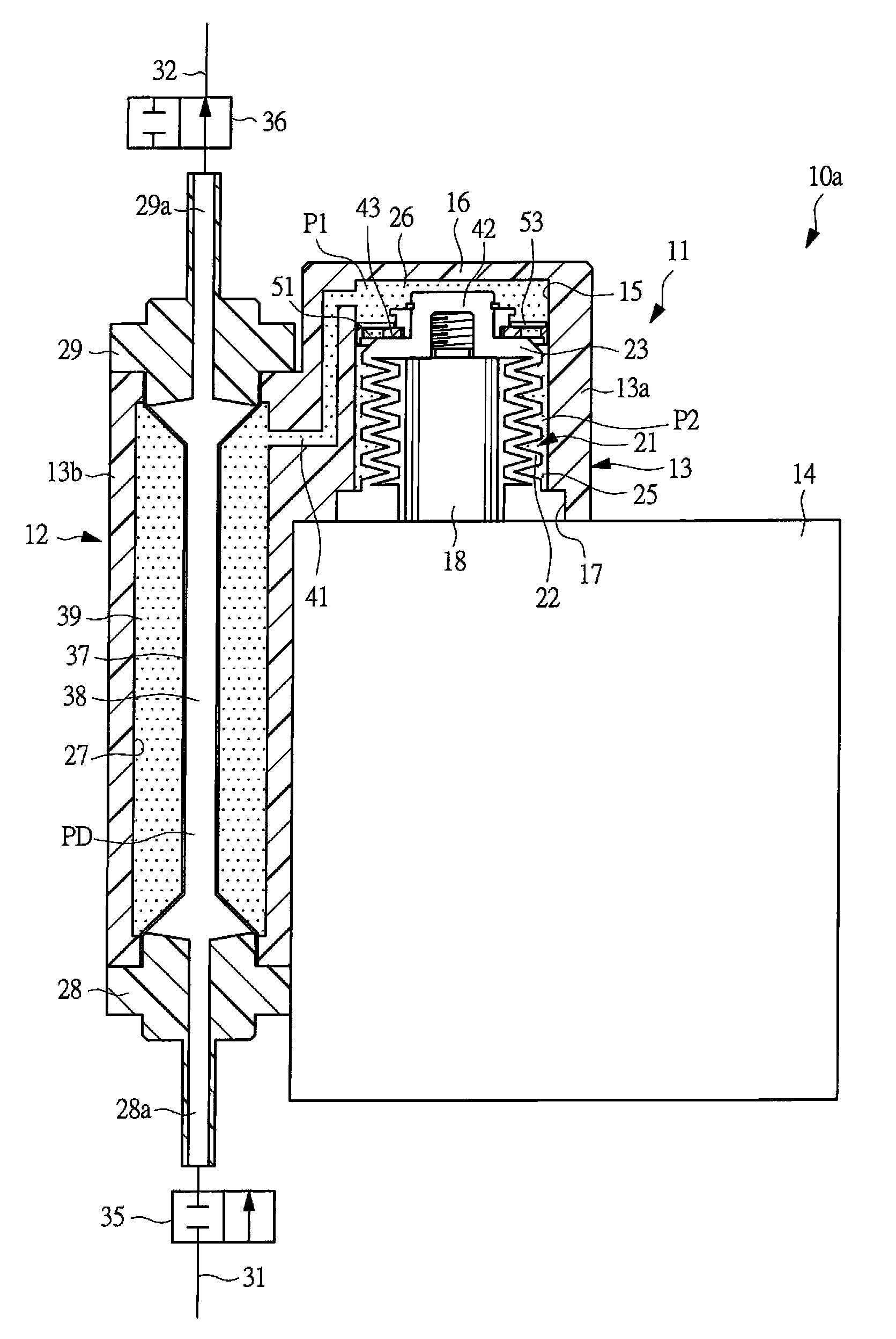
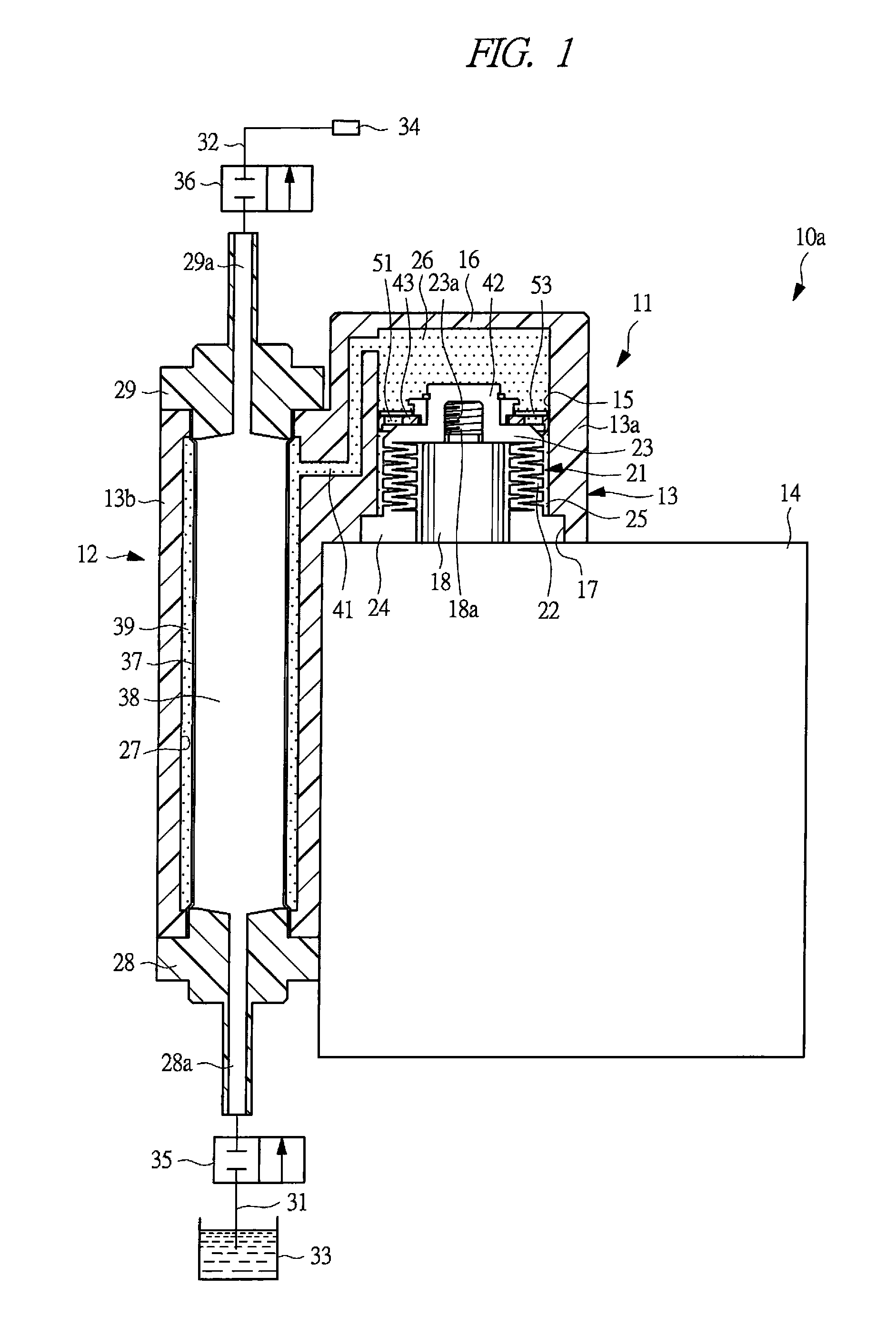
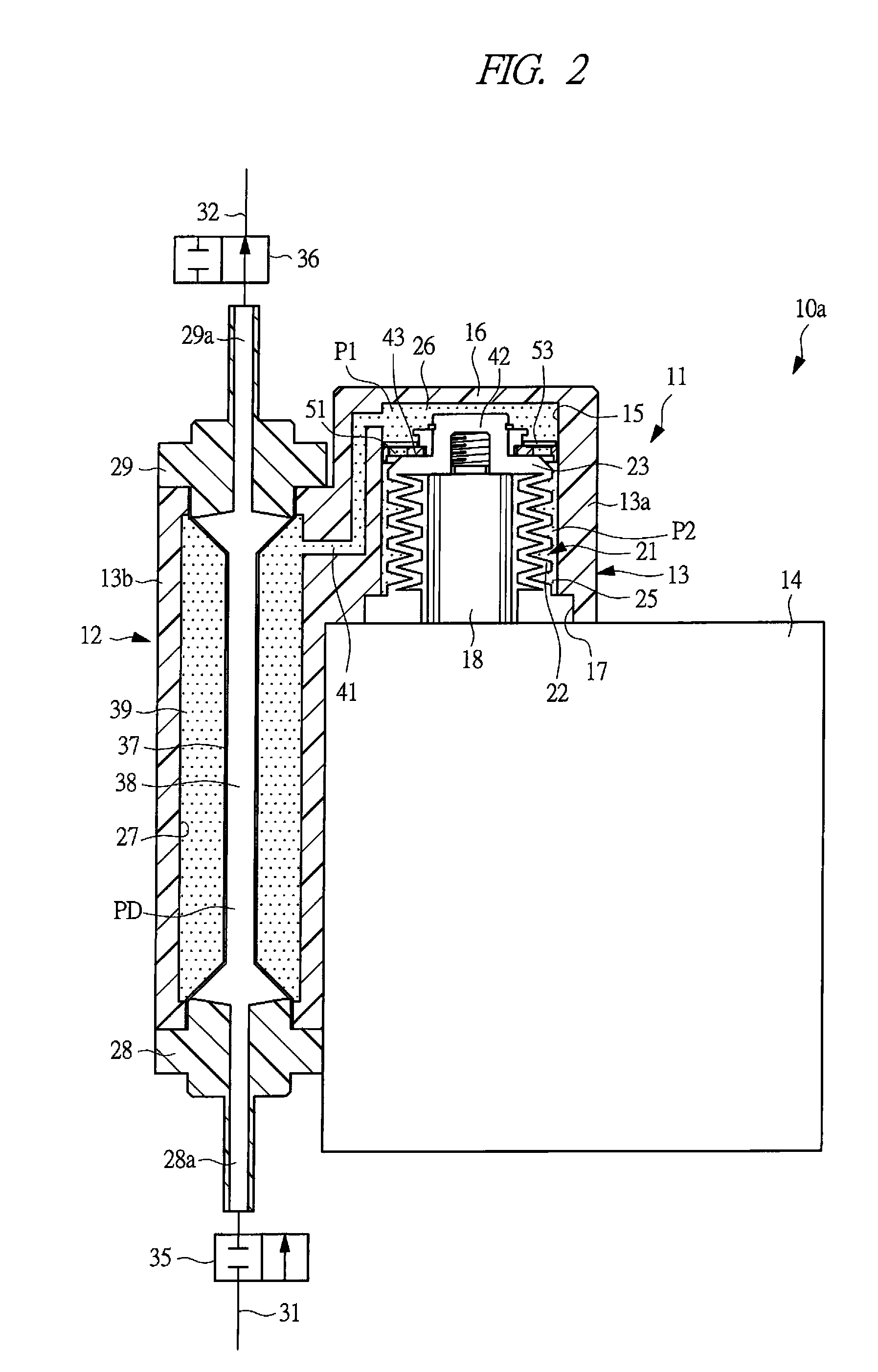
[0051]A liquid supply device 10a shown in FIGS. 1 to 3 comprises a drive pump 11 and a liquid pump 12. The drive pump 11 has a housing 13a for drive, and the liquid pump 12 has a housing 13b for liquid. Both of the housings 13a and 13b are unitized to form a housing member 13, and the housing member 13 is attached to a drive unit 14. A cylindrical receiving hole 15 is formed inside the housing 13a for drive, and one end portion of the housing 13a is a blockage end closed by a blockage wall 16, and an opening portion 17 is formed in the other end of the housing 13a.
[0052]A drive rod 18 is linearly reciprocably mounted inside the housing 13a, and reciprocates by an unshown drive apparatus that comprises an electric motor or a pneumatic cylinder, etc. incorporated into the drive unit 14. Her...
PUM
 Abstract
Description
Claims
Application Information