Ergonomic, lighted uterine manipulator with cautery

a lighted, ergonomic technology, applied in the field of ergonomic uterine manipulators, can solve the problems of increasing the time of uterine dissection, affecting the efficiency of uterine dissection, and the difficulty of identifying the cervical cup edges and the targeted fornices, and facilitating the benefits and convenience. , the effect of enhancing uterine manipulation

Active Publication Date: 2013-12-10
LSI SOLUTIONS
View PDF53 Cites 39 Cited by
  • Summary
  • Abstract
  • Description
  • Claims
  • Application Information

AI Technical Summary

Benefits of technology

[0011]The two main design goals for this invention were to develop a safe and truly effective technology for use under relevant surgical conditions, and then to provide a product that is easily learned and successfully deployed by surgeons and their assistants without requiring exhaustive training. The technology is designed to be more readily installed, intuitively obvious to position, and comfortable to hold. A compelling feature of this invention, to enable ease of installation, is the provision of an isolated slender customized sound which is readily installed through the cervix into the uterus. This compact sound acts as a guide over which the cervical engaging cup can be subsequently passed. The ability to install the sound alone readily enables its installation into the uterus under direct visualization within the vagina. This separate sound also makes its secure engagement to the uterus easy by turning the knurled knob to rotate the anchor. Since known alternative designs provide their uterine insertion elements already attached to the rest of their device, their distal insertion means is burdened with obstructing elements, such as their preinstalled balloons and cervical cups. Non-separated insertion features make device installation difficult to visualize and perform. The transvaginal installation of alternative products is significantly encumbered by having their devices' distal insertion components with unnecessary pre-attached larger diameter features. The provision of a physically separated engagement cup that slides over the installed sound makes the cervical cup installation fast and effective.
[0012]While many previous products reportedly can be used to surgically delineate the vaginal fornices and manipulate the uterus, this innovation simplifies and enhances critical anatomic identification and tissue mobilization in routine and complex minimally invasive gynecologic surgical interventions. This technology can become a cost-effective preferred means for surgeons striving to potentially improve patient outcomes and reduce procedure times.
[0013]This novel technology consists of four primary components, which are further provided in a variety of sizes to accommodate variations in patient anatomy. An ergonomic hand-held cervical engagement device with a custom co-axial handle at its proximal end is connected by an atraumatic shaft incorporating a sliding flexible vaginal occluder to an angled cup to receive the cervix at its distal end. Passageways within this cervical engagement device provide for receipt of additional components and features. To effectively engage and pivot the body of the uterus within the pelvis, an angled shaft (or sound) is provided to pass through the cervical engagement device, through the cervical canal and into the cavity in the body of the uterus, where a rotational anchor can be deployed to secure the shaft to the uterus. Additional options provided with this technology include the provision of light at the distal cervical cup to transilluminate and better visualize tissues of the vaginal fornix area and an energized dissection means to help dissect the uterus from the vagina.
[0014]A ridge on the handle of the cervical engagement device indicates the direction of the angled cervical cup and angled shaft of the sound. By simply rotating the handle, the cervical cup and angled sound rotate to pivot the uterus in the direction of the indicator ridge. When the indicator ridge is oriented up, the body of the uterus is pivoted up (i.e., ante flexed) to provide access for the posterior colpotomy (i.e., vaginal incision) dissection. When the ridge is down, the uterus is retroflexed to enable development of the bladder flap and anterior colpotomy; indicator ridge orientation to either side, enables ipsilateral uterine body pivoting for contra-lateral uterine blood vessel transillumination and dissection, along with colpotomy completion. When the indicator ridge orientation faces the patient's right side, the uterine body pivots towards the patient's right side, exposing the left side uterine arteries and veins (and potentially transilluminating them) and distracting these important blood vessels away from the left ureter. By creating further distance between these blood vessels and the adjacent ureter, this simple technique of rotating the coaxial handle to displace the uterus reduces the potential risk of ureteral injury during dissection. By rotating the indicator ridge to the opposite side, this same maneuver can expose the left uterine arteries, move them away from the left ureter and enable completion of the colpotomy.
[0017]The vaginal illuminator is an option that can be used at the surgeon's discretion with this technology for the provision of transillumination light delivered through the distal cervical cup. Using light to transilluminate or pass through targeted tissues is a common practice in minimally invasive surgery. Vaginal illumination is commonly employed in many routine gynecologic diagnostic and therapeutic interventions. When using commercially available alternative uterine manipulation products, it is frequently difficult to localize the vaginal fornices during laparoscopic hysterectomy. During this critical dissection, many very skilled and experienced surgeons have described the sense of getting lost deep in this pelvic anatomy. In accordance with an aspect of this invention, transillumination via the fiber optic vaginal illuminator through the transparent seal of the distal cervical cup can make identifying the cervical cup edges and the targeted fornices much easier. This transillumination technique may allow the surgical team to identify internal tissue structures, such as blood vessels, that lie within solid tissue planes. With this lighting option, important internal tissue elements can be differentiated through direct video imaging.
[0018]The resection or removal of the uterus requires the cervical region of the uterus to be dissected free or amputated from its attachments at the upper forniceal area of the vagina. This dissection is typically approached from one of two directions: “from below” or “from above.” If the surgeon stands down between the patient's legs and passes dissecting instruments from outside towards the inside up through the vagina, as in a vaginal hysterectomy, this dissection is considered to be “from below.” When dissecting is performed using the instruments placed “from above,” the instruments are oriented in the preferred direction from the inside of the peritoneal cavity towards the vagina, as in traditional open surgery or in total laparoscopic hysterectomy, the surgeon can stay at the patient's side adjacent to the abdomen. By providing this new technology that also provides an energized dissection function, this unique approach facilitates the benefits and convenience of providing the dissection coming in from below along with the safety and ergonomics of viewing the dissection from the above, laparoscopic perspective. Thus, this technology provides for direct dissection of the vaginal cuff up through the vagina, while simultaneously viewing and performing laparoscopic surgery from above.

Problems solved by technology

Gynecologic surgeons have repeatedly reported that remote uterine dissection, especially the vaginal cuff separation, remains a significant challenge despite multiple currently available products from other companies.
Even with the availability and use of earlier uterine manipulator products, difficulties with cervical and uterine dissections are frequently associated with iatrogenic injuries to patients' bladders, ureters, vaginal vaults and surrounding tissues.
Difficulties with this dissection often add substantial time to these operative procedures and are one of the leading causes of the need to convert laparoscopic procedures to more invasive open laparotomies.
Since known alternative designs provide their uterine insertion elements already attached to the rest of their device, their distal insertion means is burdened with obstructing elements, such as their preinstalled balloons and cervical cups.
Non-separated insertion features make device installation difficult to visualize and perform.
The transvaginal installation of alternative products is significantly encumbered by having their devices' distal insertion components with unnecessary pre-attached larger diameter features.

Method used


Image

  • Ergonomic, lighted uterine manipulator with cautery
  • Ergonomic, lighted uterine manipulator with cautery
  • Ergonomic, lighted uterine manipulator with cautery

Examples


Embodiment Construction

[0050]While the invention has been described in connection with certain presently preferred embodiments thereof, those skilled in the art will recognize that many modifications and changes may be made without departing from the broad scope of the invention, which is intended to be defined solely by the appended claims.

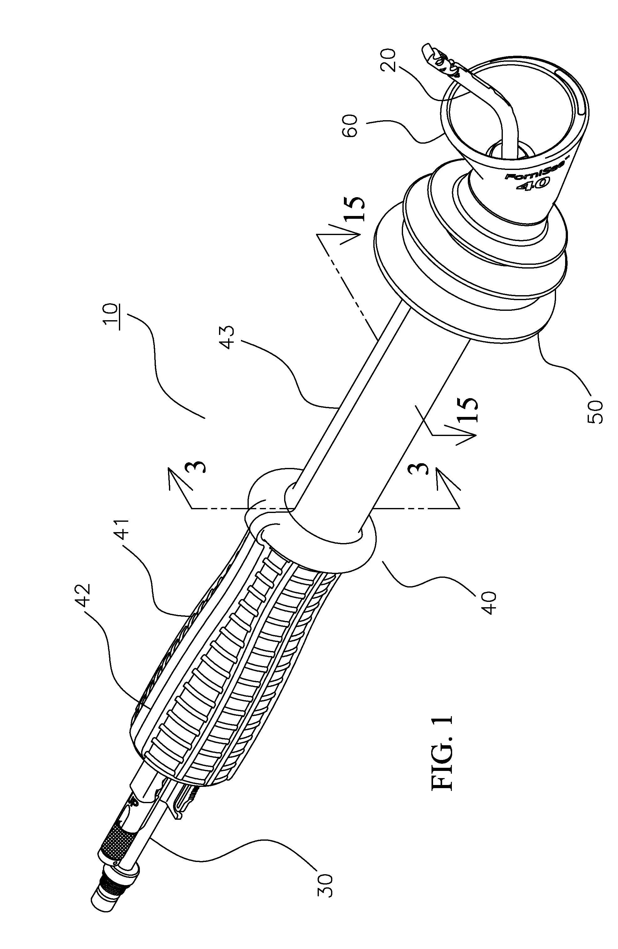
[0051]Referring to FIG. 1, a perspective view of a uterine manipulator 10 is shown, comprised of a sound 20 and a light wand 30 accepted within and housed by a device 40. The sound 20 and light wand 30 are generally manufactured such that they are reusable and preferably comprised of rigid, sterilizable, and cleanable materials such as stainless steels and the like. The device 40 is typically disposable and generally comprised of sterilizable molded polymers.

[0052]Evident in the device 40 are a proximally located textured handle 41 imparting a tactile surface for ease of physical manipulation of manipulator 10 and device 40, an indicator ridge 42 to delineate manipulat...


PUM


Abstract

A uterine manipulator includes a sound and a body. The sound has a selectively actuatable anchor disposed proximate a distal end and an operating mechanism spaced from the anchor for controlling actuation of the anchor. The body has a passage therethrough adapted to receive the sound passed proximally through the body to a position in which the operating mechanism is accessible proximally of the body and the anchor extends distally.

Description

BACKGROUND OF THE INVENTION[0001]Despite decades of commercial availability of a wide variety of transvaginally placed uterine manipulators, the need still exists for more effective and ergonomic surgical instruments to optimize the remote manipulation of a patient's vaginal, cervical and uterine tissues during modern minimally invasive gynecologic procedures. Naturally occurring openings in the body, like the vagina, urethra, anus and mouth, provide places to engage internal tissues without the requirement of cutting a hole in the patient's skin. Utilization of the vaginal canal to surgically access the cervix and uterus is routinely part of modern health care. As major gynecologic therapeutic interventions continue to become less invasive using fewer and smaller incisions, without better means for uterine control and mobilization, such procedures will become increasingly difficult to perform and require substantially more operative time, while potentially compromising patient safe...

Claims


Application Information

Patent Timeline
Patent Type & Authority Patents(United States)
IPC IPC(8): A61B17/42
CPCA61B17/4241A61B19/5202A61B2017/00323A61B2017/00433A61B2017/00455A61B2018/1412A61B2019/5206A61B90/30A61B2090/306
Inventor SAUER, JUDE S.
Owner LSI SOLUTIONS
Why Eureka
Try Eureka