Supercharge Your Innovation With Domain-Expert AI Agents!

Phase plate having fine periodic structure smaller than visible light wavelength and projection image display apparatus

a periodic structure and phase plate technology, applied in the field of phase plates, can solve the problems of difficult to uniformly process the oblique grating shape, difficult to release the mold after the nanoimprint molding method, and difficult to manufacture the fine structure, etc., and achieve the effect of convenient manufacturing

Inactive Publication Date: 2013-12-10
CANON KK
View PDF2 Cites 0 Cited by
  • Summary
  • Abstract
  • Description
  • Claims
  • Application Information

AI Technical Summary

Benefits of technology

The present invention provides a phase plate that can be easily made and has an optical axis in a different direction than the surface of a transparent substrate. The phase plate has a periodic structure that allows light to enter with a specific phase difference. The structure is designed to reduce its volume occupation rate as it moves further from the substrate surface. The phase plate is formed on both the surface of the substrate and a separately formed film, and can provide light with a predetermined phase difference for a given design wavelength. The angle between the center of a unit periodic structure and the substrate surface is important for achieving the desired phase difference. The technical effect of the invention is to provide a more efficient and effective tool for controlling the phase of light in a transparent substrate.

Problems solved by technology

However, it is difficult to manufacture the fine structure as disclosed in Japanese Patent Laid-Open No. 2004-163450.
However, since the process size is smaller than or equal to a wavelength and the periodic structure is inclined with respect to an element surface, it is difficult to release the mold after the molding in the method of the nanoimprint.
Even when the etching is used, the shape needs to be fabricated in an oblique direction with respect to the substrate surface, and therefore it is difficult to uniformly process the oblique grating shape as disclosed in Japanese Patent Laid-Open No. 2004-163450.

Method used


Image

  • Phase plate having fine periodic structure smaller than visible light wavelength and projection image display apparatus
  • Phase plate having fine periodic structure smaller than visible light wavelength and projection image display apparatus
  • Phase plate having fine periodic structure smaller than visible light wavelength and projection image display apparatus

Examples


embodiment 1

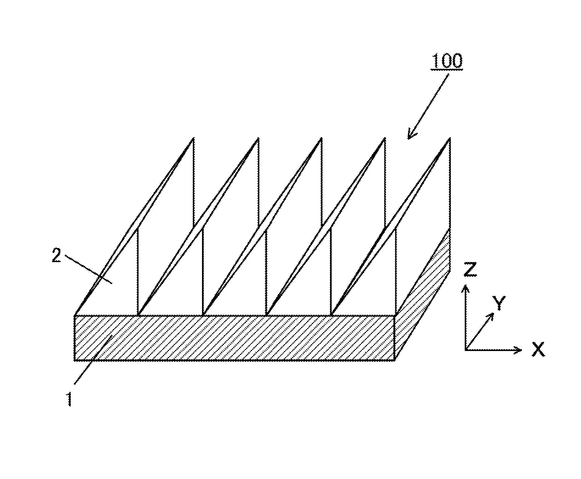
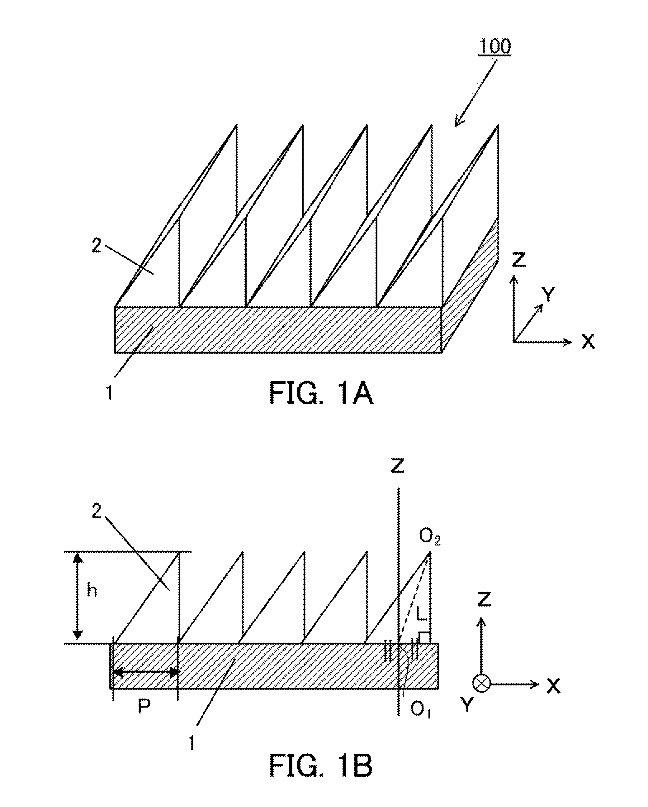
[0029]First of all, a phase plate in Embodiment 1 of the present invention will be described. FIG. 1A is a schematic diagram illustrating a configuration of a phase plate 100 in the present embodiment. FIG. 1B is a diagram illustrating a cross-sectional shape in an xz plane of FIG. 1A. The phase plate 100 has a grating period P which is shorter than or equal to a visible light wavelength, and is configured to include a periodic structure 2 (a one-dimensional grating) having a grating height h that is formed on a substrate surface of a transparent substrate 1. The phase plate 100 is also configured to give a phase difference from ¼ to ¾ wavelength to light having a predetermined design wavelength that is a visible light wavelength, which enters the substrate surface vertically. In other words, an optical axis of this phase plate 100 is a direction that is different from a normal direction of the substrate surface of the transparent substrate 1, i.e. the direction of the optical axis ...

embodiment 2

[0050]Next, a phase plate in Embodiment 2 of the present invention will be described. FIG. 11A is a schematic diagram illustrating a configuration of a phase plate 200 of the present embodiment. FIG. 11B is a diagram illustrating a cross-sectional shape in the xz plane of FIG. 11A. The phase plate 200 includes a periodic structure 2 (a first periodic structure) and a periodic structure 3 (a second periodic structure) that are formed on a first substrate surface 1a and a second substrate surface 1b (both surfaces) of the transparent substrate 1, respectively. The phase plate 200 is, similarly to Embodiment 1, configured so as to provide a phase difference from ¼ wavelength to ¾ wavelength for light having a predetermined design wavelength, and has an optical axis in a direction different from normals of the first substrate surface and the second substrate surface of the transparent substrate 1. The periodic directions of the periodic structures 2 and 3 are parallel to each other (in ...

embodiment 3

[0056]Next, a phase plate in Embodiment 3 of the present invention will be described. FIG. 13A is a schematic diagram illustrating a configuration of a phase plate 300 in the present embodiment. FIG. 13B is a diagram illustrating a cross-sectional shape in the xz plane of FIG. 13A. A fine periodic structure 2 is formed on an upper surface of the transparent substrate 1. A layer 4 that has a refractive index different from a refractive index of a material constituting the periodic structure 2 is formed on the periodic structure 2. It is preferred that a height h4 of the layer 4 be set to lower than or equal to a grating height h3 of the periodic structure 2. In addition, the refractive index of the layer 4 is higher than the refractive index of the periodic structure 2. Therefore, the height of whole of the periodic structure 2 is increased to be able to enlarge a phase difference of the phase plate. In the present embodiment, the refractive index of the periodic structure 2 does not...


PUM


Abstract

A phase plate includes a transparent substrate and a periodic structure formed on a substrate surface of the transparent substrate. The phase plate is configured to provide light having a predetermined design wavelength that vertically enters the substrate surface with a phase difference from ¼ wavelength to ¾ wavelength. The periodic structure is configured to reduce a volume occupation rate with increasing distance from the transparent substrate, and the periodic structure has a height of at least 200 nm. An angle between a first direction in which a center of a width of a unit periodic structure at a position closest to the substrate surface is connected with a center of a width of a unit periodic structure at a position farthest from the substrate surface and a normal direction of the substrate surface is from 5 degrees to 30 degrees.

Description

BACKGROUND OF THE INVENTION[0001]1. Field of the Invention[0002]The present invention relates to a phase plate, and more particularly to a phase plate having a fine periodic structure smaller than a visible light wavelength.[0003]2. Description of the Related Art[0004]Previously, as an optical element that gives a phase difference with respect to a transmission linear polarized light, a phase plate such as a ¼ wavelength plate or ½ wavelength plate has been known. Furthermore, there is a phase plate that has an optical axis in an arbitrary direction inclined from a surface normal direction. Such a phase plate is for example used in a projection image display apparatus to compensate a phase shift generated by a polarization beam splitter, an image display element, or the like, and therefore it has an effect that a light leakage in a projection image is reduced and that the contrast of the projection image is improved.[0005]The phase plate is manufactured by using a fine structure hav...

Claims


Application Information

Patent Timeline
Patent Type & Authority Patents(United States)
IPC IPC(8): H01J3/14
CPCG02B5/1809G02B5/1871
Inventor YAMAGUCHI, YUTAKA
Owner CANON KK
Features
  • R&D
  • Intellectual Property
  • Life Sciences
  • Materials
  • Tech Scout
  • Unparalleled Data Quality
  • Higher Quality Content
  • 60% Fewer Hallucinations
Learn More