Mixing element and an exhaust system for an internal combustion engine

a technology of mixing element and exhaust system, which is applied in the direction of machines/engines, mechanical equipment, transportation and packaging, etc., can solve the problems of clinging to the colder walls of the tube, affecting the mixing of the media, and affecting the mixing effect of the media

Active Publication Date: 2013-12-17
EMCON TECHNOLOGIES GERMANY (AUGSBURG) GMBH
View PDF12 Cites 21 Cited by
  • Summary
  • Abstract
  • Description
  • Claims
  • Application Information

AI Technical Summary

Benefits of technology

[0005]According to a first aspect of the invention, in a mixing element of the kind mentioned at the outset, this is achieved in that the deflector elements of at least two immediately adjacent first rows are inclined in the same direction. It has been found totally surprisingly in tests that although the deflector elements of the adjacent first rows are inclined in the same way, the mixing element according to the invention achieves better mixing values than the mixing element in the prior art. Further, the mixing element is simpler to produce because for chamfering the closely adjacent deflector elements, it is simpler if neighboring deflector elements can be bent in the same direction. The invention in particular allows a more uniform distribution of a liquid medium in a gas stream to be reached. This is of advantage above all in an exhaust system of an internal combustion engine having a SCR catalytic converter, which requires ammonia for the conversion of nitrogen oxides. For this purpose, an aqueous urea solution is introduced into the exhaust system. It is important to note that even the largest drops of the urea solution are vaporized upstream of the SCR catalytic converter and are converted into ammonia gas by thermolysis. Any residual drops might damage the catalytic converter substrate or cling to the colder walls of the tube through which the exhaust gas flows. This may result in the deposited urea chipping off and causing damage to the catalytic converter. This is prevented by the mixing element according to the invention. Owing to their low thermally active mass, the deflector elements heat up quickly in the hot exhaust gas stream and small droplets are vaporized when they come into contact with the surface of the deflector elements. Larger drops impinge on the surface of the deflector elements and, due to their high kinetic energy, burst into many small droplets which are likewise reliably vaporized. The orientation of the rows described in the present invention need not necessarily lead to a very exact parallel orientation. A slightly oblique position is quite possible.
[0016]A second aspect of the invention provides a mixing element having a grid which includes a plurality of rows parallel to each other and a plurality of deflector elements which project from the grid and are inclined in relation to the grid plane normal. At least one field has deflector elements inclined in the same direction which is formed by at least four adjacent deflector elements. Here, not all of the deflector elements of the field are arranged in one row. In this connection, the term “adjacent” means that each deflector element is positioned immediately next to at least one other deflector element. This configuration having one or more fields of deflector elements inclined in the same direction also allows a mixing of two media to be obtained which is improved as compared to the prior art.
[0020]According to a third aspect of the invention, the object initially mentioned is achieved by a mixing element, in particular for arrangement in an exhaust system of an internal combustion engine. The mixing element includes a grid with a plurality of rows parallel to each other and a plurality of deflector elements which project from the grid and are inclined in relation to the grid plane normal. At least one eddy-forming portion is provided which is constituted by at least four adjacent fields which are each made up of a plurality of adjacent deflector elements inclined in the same direction. The fields are arranged in a circular manner with respect to the inclination of the deflector elements thereof, by deflector elements of the portion adjacent in the direction of rotation of the eddy being oriented to be turned through a maximum of 90 degrees in relation to each other. The deflector elements which are part of the portion cause the media to rotate and thereby enhance the mixing thereof. Here, the entire area of the mixing element may be formed as one large eddy-forming portion or only a central part of the mixing element. It is also conceivable to arrange a plurality of eddy-forming portions in such a way that a plurality of eddies are formed that are oriented in the same direction or in opposite directions.
[0022]The angle of inclination of the deflector elements should amount to between 10 degrees and 60 degrees to the grid plane normal, preferably about 45 degrees. In this way, a high swirling and thus a good mixing of the media is achieved. At the same time, the counterpressure produced in the flowing medium by a mixing element of such type is comparatively low.
[0023]A particularly simple configuration, which is therefore inexpensive to produce, is obtained in that the grid is formed by a plurality of flat first and second webs, the first webs being arranged perpendicularly to the second webs.
[0025]In the mixing element according to the invention, low manufacturing costs are attained in that the first and second webs are inserted into each other and welded or soldered to each other.

Problems solved by technology

Any residual drops might damage the catalytic converter substrate or cling to the colder walls of the tube through which the exhaust gas flows.
This may result in the deposited urea chipping off and causing damage to the catalytic converter.

Method used


Image

  • Mixing element and an exhaust system for an internal combustion engine
  • Mixing element and an exhaust system for an internal combustion engine
  • Mixing element and an exhaust system for an internal combustion engine

Examples


Embodiment Construction

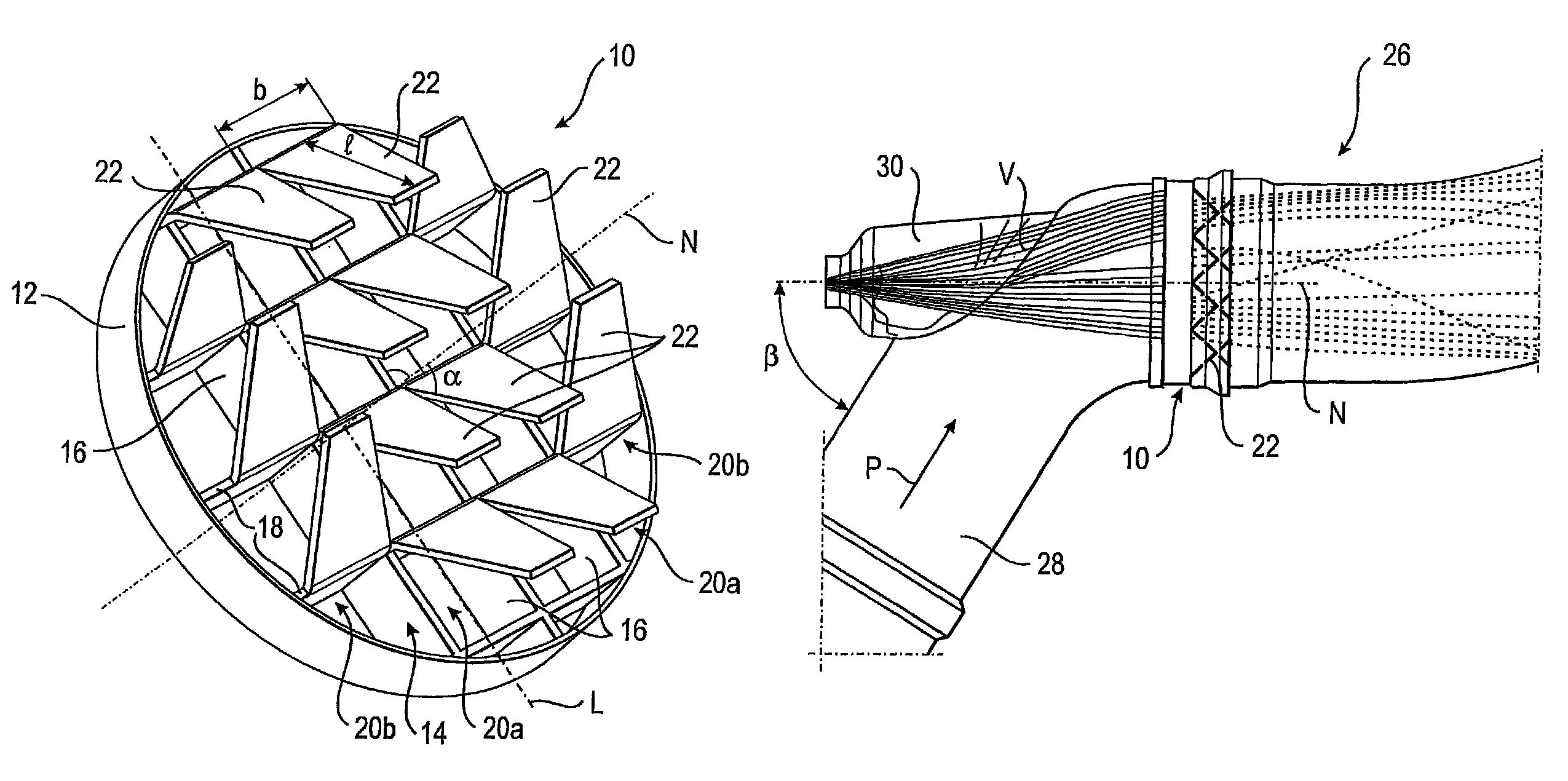
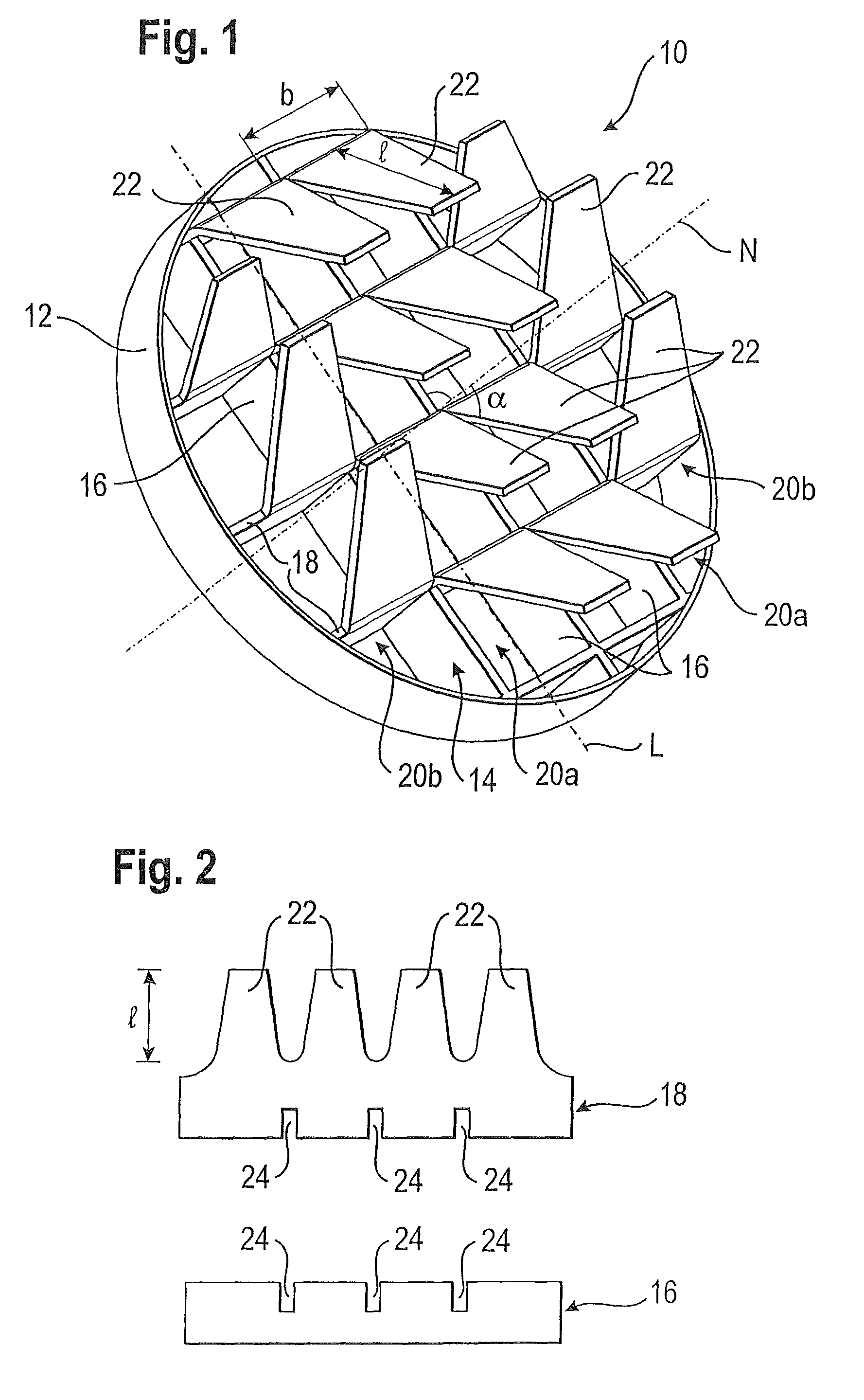
[0049]FIG. 1 shows a stationary mixing element 10 according to the invention which includes a grid 14 which is delimited by an annular frame 12 and is formed by a plurality of first webs 16 having a parallel orientation and second webs 18 arranged perpendicularly thereto. The first webs 16 define a plurality of rows 20a, 20b which are parallel to each other, the two outermost rows 20b being delimited on the outer side by the frame 12 itself. It would, of course, also be possible to configure the rows 20a, 20b so as not to be precisely parallel.

[0050]Projecting from the grid 14 is a plurality of deflector elements 22 which are attached to the second webs 18, more particularly formed in one piece therewith (and thus with the grid 14). The length 1 (FIG. 2) of the deflector elements 22 substantially corresponds to the width b of the rows 20a, 20b.

[0051]For the manufacture of the mixing element 10, the first webs 16 and the second webs 18 along with the deflector elements 22 are produc...


PUM

PropertyMeasurementUnit
angle of inclinationaaaaaaaaaa

Abstract

A mixing element has a grid which includes a plurality of rows parallel to each other and a plurality of deflector elements which project from the grid and are inclined in relation to the grid plane normal. All deflector elements of one row are inclined in the same direction. The deflector elements of at least two immediately adjacent first rows are inclined in the same direction. The mixing element is used in an exhaust system of an internal combustion engine.

Description

RELATED APPLICATION[0001]This application is the U.S. national phase of PCT / EP2007 / 010087, which was filed Nov. 21, 2007, which claimed priority to DE 10 2006 055 036.6, which was filed Nov. 22, 2006.FIELD OF THE INVENTION[0002]The present invention relates to a mixing element, in particular for arrangement in an exhaust system of an internal combustion engine, including a grid which includes a plurality of rows parallel to each other and a plurality of deflector elements which project from the grid and are inclined in relation to the grid plane normal, with all of the deflector elements of one row being inclined in the same direction. According to a further aspect, the present invention relates to a mixing element including a grid which includes a plurality of rows parallel to each other and a plurality of deflector elements which project from the grid and are inclined in relation to the grid plane normal, and which includes at least one field having deflector elements inclined in ...

Claims


Application Information

Patent Timeline
Patent Type & Authority Patents(United States)
IPC IPC(8): F01N1/00F01N3/00F01N3/10
CPCB01F3/04049B01F5/0451B01F5/0616F01N3/2066B01F2005/0639Y02T10/24F01N3/2892F01N2240/20F01N2610/02F01N2610/102Y02T10/12B01F23/2132B01F2025/931B01F25/3131B01F25/4315B01F25/431974
Inventor KAISER, ROLFRUSCH, KLAUSSTADLER, FLORIAN
Owner EMCON TECHNOLOGIES GERMANY (AUGSBURG) GMBH
Why Eureka
Try Eureka