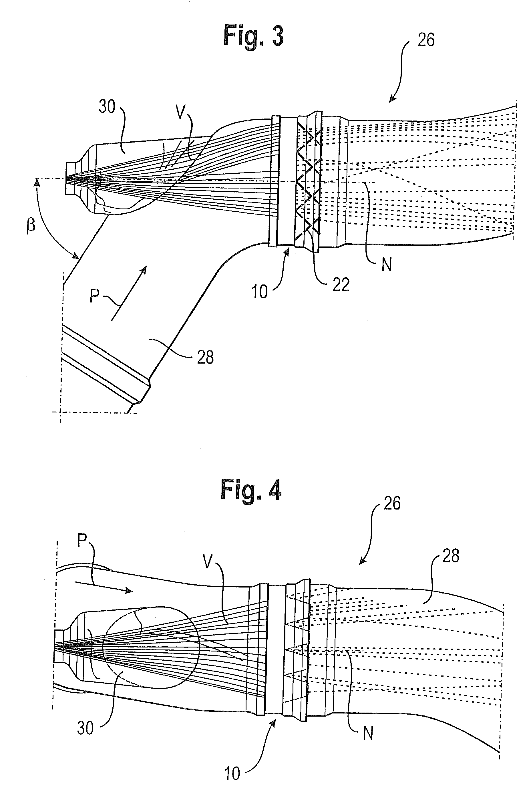
[0005]According to a first aspect of the invention, in a mixing element of the kind mentioned at the outset, this is achieved in that the deflector elements of at least two immediately adjacent first rows are inclined in the same direction. It has been found totally surprisingly in tests that although the deflector elements of the adjacent first rows are inclined in the same way, the mixing element according to the invention achieves better mixing values than the mixing element in the prior art. Further, the mixing element is simpler to produce because for chamfering the closely adjacent deflector elements, it is simpler if neighboring deflector elements can be bent in the same direction. The invention in particular allows a more uniform distribution of a
liquid medium in a gas
stream to be reached. This is of
advantage above all in an exhaust
system of an
internal combustion engine having a SCR
catalytic converter, which requires
ammonia for the conversion of
nitrogen oxides. For this purpose, an aqueous
urea solution is introduced into the exhaust system. It is important to note that even the largest drops of the
urea solution are vaporized upstream of the SCR catalytic converter and are converted into
ammonia gas by thermolysis. Any residual drops might damage the catalytic converter substrate or cling to the colder walls of the tube through which the
exhaust gas flows. This may result in the deposited urea chipping off and causing damage to the catalytic converter. This is prevented by the mixing element according to the invention. Owing to their low thermally active
mass, the deflector elements heat up quickly in the hot
exhaust gas stream and small droplets are vaporized when they come into contact with the surface of the deflector elements. Larger drops impinge on the surface of the deflector elements and, due to their
high kinetic energy, burst into many small droplets which are likewise reliably vaporized. The orientation of the rows described in the present invention need not necessarily lead to a very exact parallel orientation. A slightly oblique position is quite possible.
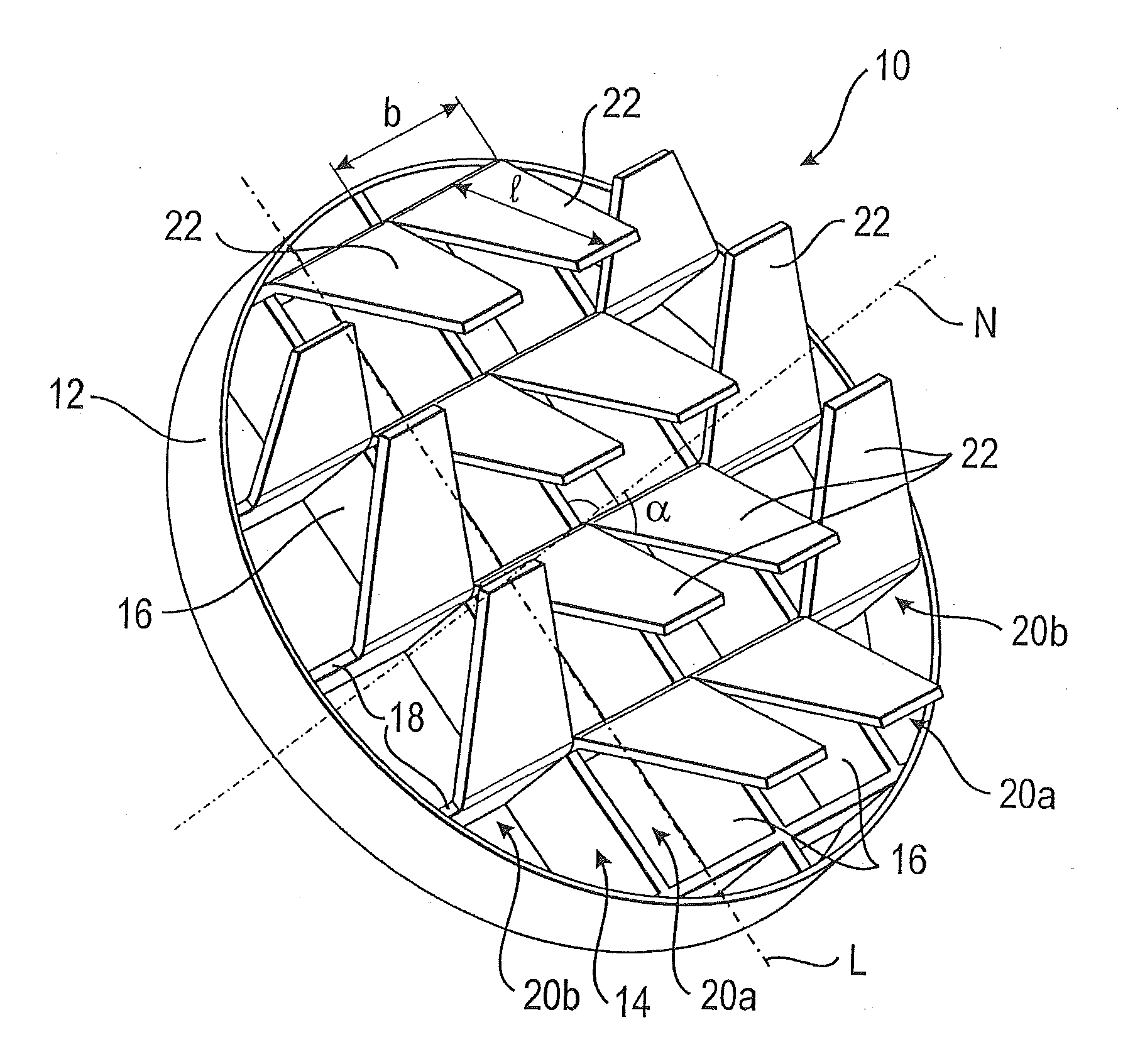
[0016]A second aspect of the invention provides a mixing element having a grid which includes a plurality of rows parallel to each other and a plurality of deflector elements which project from the grid and are inclined in relation to the grid plane normal. At least one field has deflector elements inclined in the same direction which is formed by at least four adjacent deflector elements. Here, not all of the deflector elements of the field are arranged in one row. In this connection, the term “adjacent” means that each deflector element is positioned immediately next to at least one other deflector element. This configuration having one or more fields of deflector elements inclined in the same direction also allows a mixing of two media to be obtained which is improved as compared to the prior art.
[0020]According to a third aspect of the invention, the object initially mentioned is achieved by a mixing element, in particular for arrangement in an exhaust system of an internal
combustion engine. The mixing element includes a grid with a plurality of rows parallel to each other and a plurality of deflector elements which project from the grid and are inclined in relation to the grid plane normal. At least one eddy-forming portion is provided which is constituted by at least four adjacent fields which are each made up of a plurality of adjacent deflector elements inclined in the same direction. The fields are arranged in a circular manner with respect to the inclination of the deflector elements thereof, by deflector elements of the portion adjacent in the direction of rotation of the eddy being oriented to be turned through a maximum of 90 degrees in relation to each other. The deflector elements which are part of the portion cause the media to rotate and thereby enhance the mixing thereof. Here, the entire area of the mixing element may be formed as one large eddy-forming portion or only a central part of the mixing element. It is also conceivable to arrange a plurality of eddy-forming portions in such a way that a plurality of eddies are formed that are oriented in the same direction or in opposite directions.
[0022]The
angle of inclination of the deflector elements should amount to between 10 degrees and 60 degrees to the grid plane normal, preferably about 45 degrees. In this way, a high swirling and thus a good mixing of the media is achieved. At the same time, the counterpressure produced in the flowing medium by a mixing element of such type is comparatively low.
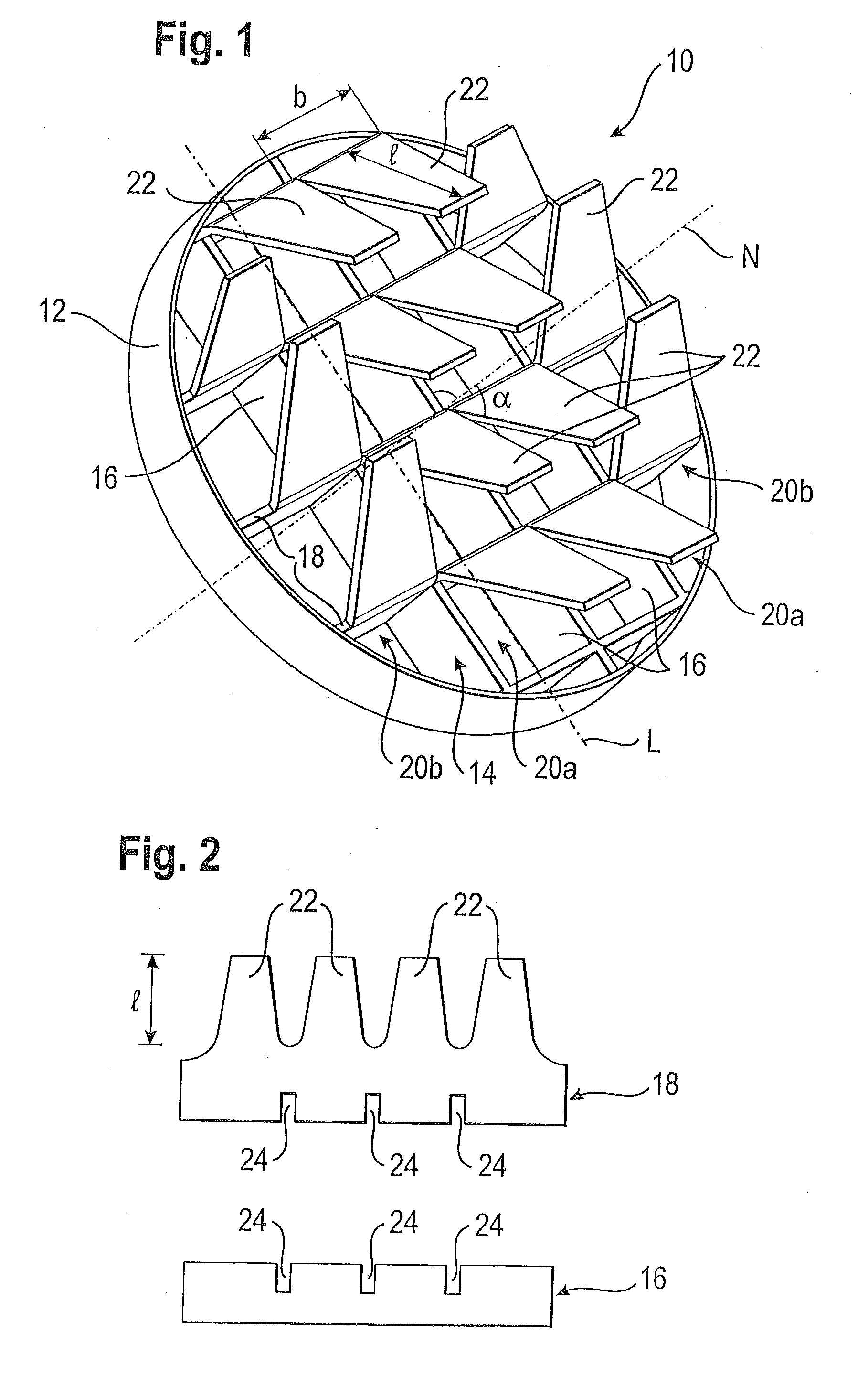
[0023]A particularly simple configuration, which is therefore inexpensive to produce, is obtained in that the grid is formed by a plurality of flat first and second webs, the first webs being arranged perpendicularly to the second webs.
[0025]In the mixing element according to the invention, low manufacturing costs are attained in that the first and second webs are inserted into each other and welded or soldered to each other.

