
Reservoir tank and brake device using the reservoir tank

a technology of reservoir tank and brake device, which is applied in the direction of fluid couplings, rotary clutches, couplings, etc., can solve the problems of common use, cumbersome work, and potential misuse of instruments, and achieve the suppression of instrument misuse, increase in volume, and reliably absorb

Active Publication Date: 2013-12-17
BOSCH CORP
View PDF8 Cites 2 Cited by
  • Summary
  • Abstract
  • Description
  • Claims
  • Application Information

AI Technical Summary

Benefits of technology

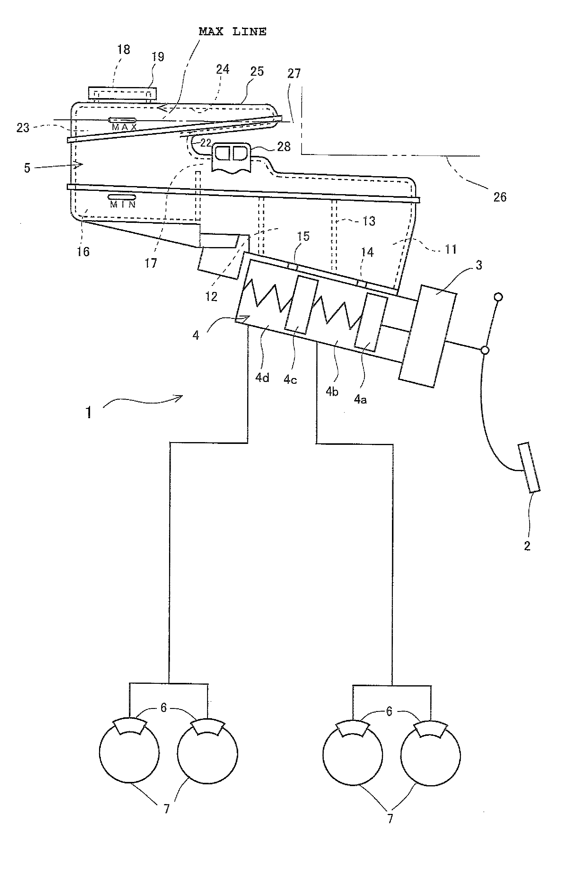
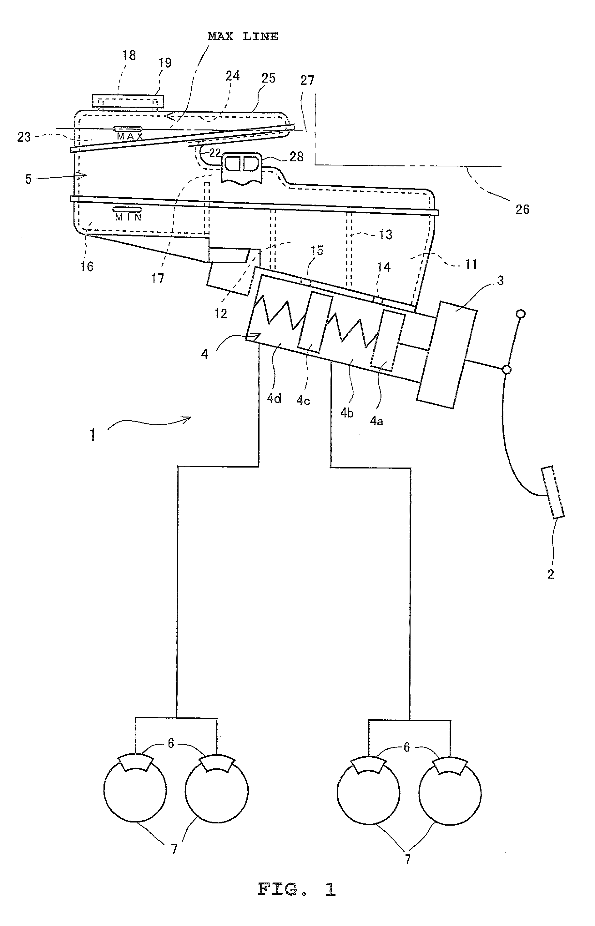
[0011]The present invention has been made in light of this circumstance, and it is an object thereof to provide a reservoir tank, and a brake device using the reservoir tank, with which the volume of an air chamber above hydraulic fluid can be increased without changing the height of a hydraulic fluid supply opening from a MAX line.
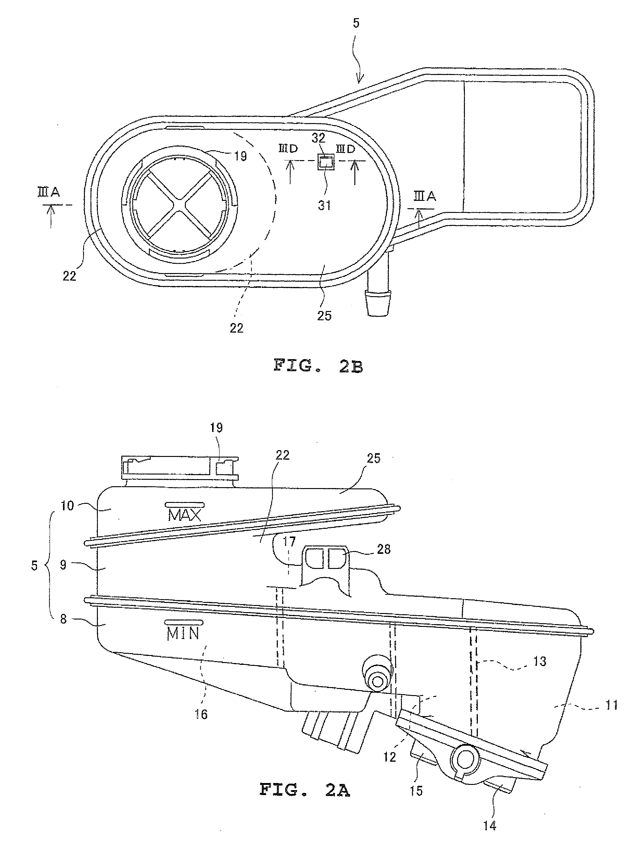
[0018]According to the reservoir tank of the present invention configured in this manner, the volume-augmented chamber forming portion that has inside the volume-augmented chamber that is communicated with the chamber of the cylindrical portion is disposed in the cylindrical portion that is disposed between the hydraulic fluid supply opening and the hydraulic fluid supply portion, to which the hydraulic fluid is supplied from this hydraulic fluid supply opening and which supplies this hydraulic fluid to the hydraulic fluid storage chamber, and has the chamber that is communicated with the hydraulic fluid supply portion, and at least part of this volume-augmented chamber is positioned above the MAX line of the hydraulic fluid. Thus, in a state where the hydraulic fluid fills the reservoir tank to the MAX line, a new air chamber can be formed inside at least part of the volume-augmented chamber in addition to the air chamber that is formed inside the cylindrical portion. Consequently, when the temperature of the hydraulic fluid rises and the volume of the hydraulic fluid increases because of the use environment described above, this increased volume change in the hydraulic fluid can be absorbed by the conventional air chamber and can also be absorbed by the new air chamber. As a result, even when the increase change in the volume of the hydraulic fluid is relatively large, the increase change in the volume of the hydraulic fluid can be more reliably absorbed, and a situation where the hydraulic fluid leaks out to the outside from the hydraulic fluid supply opening can be suppressed.
[0019]Further, according to the reservoir tank of the present invention, the volume-augmented chamber forming portion is disposed so as to extend horizontally or substantially horizontally from the cylindrical portion, so even when the volume-augmented chamber forming portion is disposed, the distance between the hydraulic fluid supply opening and the MAX line can be set to be the same as in a conventional reservoir used in a vehicle in which the reservoir tank of the present invention is used. Thus, as a pressure-feed filling device instrument that fills the inside of the reservoir tank with the hydraulic fluid, a conventional pressure-feed filling device instrument can be used as is, so that the pressure-feed filling device instrument does not have to be changed. Consequently, the number of types of pressure-feed filling device instruments does not increase by that amount, so when the vehicle production line is a line that continuously produces different vehicle types, various types of pressure-feed filling device instruments do not have to be prepared for the production line even when the reservoir tank having the volume-augmented chamber forming portion is used. As a result, the work of filling the reservoir tank with the hydraulic fluid becomes simple and instrument misuse can be suppressed.
[0020]Moreover, according to the reservoir tank of the present invention, the volume-augmented chamber forming portion is disposed so as to extend horizontally or substantially horizontally from the cylindrical portion and into the dead space when the reservoir tank is installed in a vehicle, so even when the volume-augmented chamber forming portion is disposed, the reservoir tank can be efficiently installed in the limited space of a relatively narrow engine room without interfering with other parts. In particular, the volume-augmented chamber forming portion is disposed so as to extend above the hydraulic fluid passage positioned between the hydraulic fluid supply portion and the hydraulic fluid storage chamber. The space above this hydraulic fluid passage becomes dead space, so the entire reservoir tank can be formed in substantially the same size as that of a conventional reservoir tank even when the volume-augmented chamber forming portion is disposed, and an increase in the size of the reservoir tank can be suppressed. Consequently, the reservoir tank can be even more efficiently installed in the limited space of the engine room.
[0021]Moreover, according to the reservoir tank of the present invention, the bottom portion of the volume-augmented chamber slants so as to become a downward slope toward the chamber inside the cylindrical portion. Thus, it becomes possible to more reliably cause the hydraulic fluid entering the inside of the volume-augmented chamber to flow toward the chamber—that is, the hydraulic fluid supply portion—when the quantity of the hydraulic fluid inside the reservoir tank decreases.
[0022]According to the brake device equipped with the reservoir tank of the present invention, even in a vehicle where the temperature of the engine room becomes relatively high, by using the reservoir tank of the present invention in the brake device, leakage of the brake fluid that is the hydraulic fluid from the hydraulic fluid supply opening can be suppressed so that the brakes can be more reliably actuated, and contamination inside the engine room can be prevented.

Problems solved by technology

Consequently, the distance between the MAX line in the reservoir tank and the hydraulic fluid supply opening variously differ, so a pressure-feed filling device instrument cannot be commonly used in the different reservoir tanks and is created depending on the type of the reservoir tank.
For this reason, there is the problem that the pressure-feed filling device instrument cannot be used as is, which necessitates changing the pressure-feed filling device instrument—that is, creating a new instrument Moreover, there is also the problem that, when the vehicle production line is a line that continuously produces different vehicle types, various types of pressure-feed filling device instruments have to be prepared for the production line, and so not only does work become cumbersome but there arises the potential to misuse an instrument.

Method used


Image

  • Reservoir tank and brake device using the reservoir tank
  • Reservoir tank and brake device using the reservoir tank
  • Reservoir tank and brake device using the reservoir tank

Examples


Embodiment Construction

[0028]Modes for implementing the present invention will be described below using the drawings. In the description below, horizontal and vertical refer to a state where a reservoir tank is installed in a horizontal or substantially horizontal vehicle, and a maximum storage level (MAX line) and a minimum storage level (MIN line) of hydraulic fluid are horizontal lines in the same state of the reservoir tank.

[0029]FIG. 1 is a view schematically showing a brake device equipped with one example of a mode of implementing a reservoir tank pertaining to the present invention.

[0030]As shown in FIG. 1, a hydraulic brake device 1 of this example is basically the same as a conventionally known common dual-system hydraulic brake device. That is, the hydraulic brake device 1 is equipped with a brake pedal 2, a booster 3, a tandem master cylinder 4, a reservoir tank 5 and brake cylinders 6.

[0031]When a driver steps on the brake pedal 2, the booster 3 is actuated to boost, by a predetermined servo ...


PUM


Abstract

Hydraulic fluid is supplied from a hydraulic fluid supply opening to a hydraulic fluid supply portion. The hydraulic fluid in the hydraulic fluid supply portion is supplied to a primary hydraulic fluid storage chamber and to a secondary hydraulic fluid storage chamber via a hydraulic fluid supply passage. An oblong cylinder-shaped portion that has a chamber is formed between the hydraulic fluid supply opening and the hydraulic fluid supply portion. Further, a volume-augmented chamber forming portion that has a volume-augmented chamber that is communicated with the chamber is disposed in this oblong cylinder-shaped portion. In that case, at least part of the volume-augmented chamber is positioned above a MAX line of the hydraulic fluid.

Description

BACKGROUND[0001]1. Technical Field[0002]The present invention relates to a reservoir tank that stores hydraulic fluid and is used in a hydraulic pressure-actuated device such as a hydraulic brake device that utilizes hydraulic pressure such as oil pressure and to the technical field of a brake device equipped with the reservoir tank.[0003]2. Related Art[0004]Conventionally, in vehicles such as automobiles, there are vehicles that employ a hydraulic brake device as a hydraulic pressure-actuated device that utilizes hydraulic pressure. In this hydraulic brake device, there is used a reservoir tank that stores hydraulic fluid supplied to a master cylinder that generates hydraulic pressure.[0005]As a conventional reservoir tank, there is known a reservoir tank that is equipped with a hydraulic fluid supply portion to which hydraulic fluid is supplied from a hydraulic fluid supply opening that is an open end of a cylindrical member via this cylindrical member, a hydraulic fluid storage c...

Claims


Application Information

Patent Timeline
Patent Type & Authority Patents(United States)
IPC IPC(8): B60T11/22
CPCB60T11/26
Inventor TAKAHASHI, TOSHIYUKI
Owner BOSCH CORP
Learn More