System and method for enhanced turbine wake mixing via fluidic-generated vortices

a technology of enhanced turbine wake and fluidic generated vortice, which is applied in the direction of liquid fuel engines, vessel construction, marine propulsion, etc., can solve the problems of overheating of the pressure side, higher process losses, and temperature deficits coming off the film-cooled turbine vanes and blades, so as to reduce the segregation effect of thermal wake, enhance mixing, and reduce aerodynamic losses

Active Publication Date: 2013-12-17
GENERAL ELECTRIC CO
View PDF10 Cites 9 Cited by
  • Summary
  • Abstract
  • Description
  • Claims
  • Application Information

AI Technical Summary

Benefits of technology

[0008]Briefly, in accordance with one embodiment, a high pressure turbine blade or vane comprises a substantially arcuate trailing edge including one or more fluid injection structures disposed therein and configured to reduce aerodynamic losses due to wake and / or shock interactions and further configured to reduce thermal wake segregation effects to a desired level.
[0009]According to another embodiment, a high pressure turbine (HPT) blade or vane comprises a crenulated trailing edge comprising one or more chevrons disposed on the pressure side, the suction side, or both the pressure side and suction side of the trailing edge and configured to enhance mixing out of wakes generated via the HPT blade or vane, such that aerodynamic losses due to corresponding wake and / or shock interactions are reduced to a desired level, and further such that corresponding thermal wake segregation effects are reduced to a desired level.
[0010]According to yet another embodiment, a high pressure turbine (HPT) blade or vane comprises a crenulated trailing edge including one or more fluid injection structures disposed therein and configured to inject a fluid into a desired trailing edge region, wherein the injected fluid interacts with a crenulated trailing edge passage fluid flow to create a streamwise vorticity from the interaction of the injected fluid and the passage fluid flow to enhance mixing out of wakes generated via the HPT blade or vane such that aerodynamic losses due to wake and / or shock interactions are reduced to a desired level, and further such that thermal wake segregation effects are reduced to a desired level.
[0011]According to still another embodiment, a high pressure turbine (HPT) wake mixing system comprises a pre-existing HPT blade or vane comprising one or more cooling holes disposed therein outside the trailing edge of the HPT blade or vane, wherein the pre-existing HPT blade or vane is re-configured with one or more geometric elements such that fluid injected from the one or more cooling holes is manipulated via the one or more geometric elements to reduce aerodynamic losses due to wake and shock interactions and further to reduce thermal wake segregation effects to a desired level.
[0012]According to still another embodiment, a high pressure turbine (HPT) wake mixing system comprises a pre-existing HPT blade or vane comprising a substantially arcuate trailing edge, and further comprising one or more cooling slots or holes disposed therein, wherein the pre-existing HPT blade or vane is re-configured with one or more fluid injection elements disposed in the substantially arcuate trailing edge such that fluid injected from the one or more fluid injection elements interacts with fluid flowing through the one or more cooling slots or holes to reduce aerodynamic losses due to wake and shock interactions and further to reduce thermal wake segregation effects to a desired level.

Problems solved by technology

This process generates higher losses, and often requires extra axial spacing between the HPT and LPT to fully mix the wakes.
The wakes coming off of the film-cooled turbine vanes and blades have temperature deficits in addition to the pressure deficit.
As a result, the pressure side of the downstream airfoil is hotter than the adjacent suction side, which may cause overheating of the pressure side.
Although fluidic injection elements / cooling holes and slots have been employed in the prior art to provide both aerodynamic performance benefits and cooling of turbine blades / vanes, such techniques have not yet successfully addressed aerodynamic losses resulting from wake and shock interactions, both steady and unsteady for transonic vanes / blades as well as unsteady losses due to wake interactions when blades / vanes are subsonic.
Further, high pressure turbines where the vanes are heavily cooled to ensure durability in high temperature environments, e.g. film and trailing edge cooling, can result in unsteady thermal wake segregation effects that lead to the unexpected heat-up of endwalls, e.g. platforms and blade / vane tips, of downstream blades / vanes.

Method used


Image

  • System and method for enhanced turbine wake mixing via fluidic-generated vortices
  • System and method for enhanced turbine wake mixing via fluidic-generated vortices
  • System and method for enhanced turbine wake mixing via fluidic-generated vortices

Examples


Embodiment Construction

[0037]According to particular embodiments such as those depicted in FIGS. 10-12 and 17-18 described in further detail herein, cooling hole wake mixing elements are disposed in a substantially arcuate thick trailing edge of a high pressure turbine (HPT) blade or vane to provide a trailing edge wake mixing scheme. Unlike conventional trailing edge wake mixing schemes that inject fluid parallel to the main flow path, these embodiments advantageously inject fluid at pitch and / or yaw angles to the main flow path to generate the desired streamwise vortices described in further detail herein.

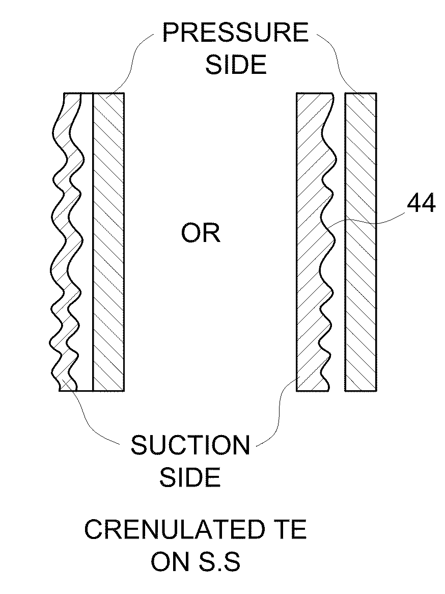
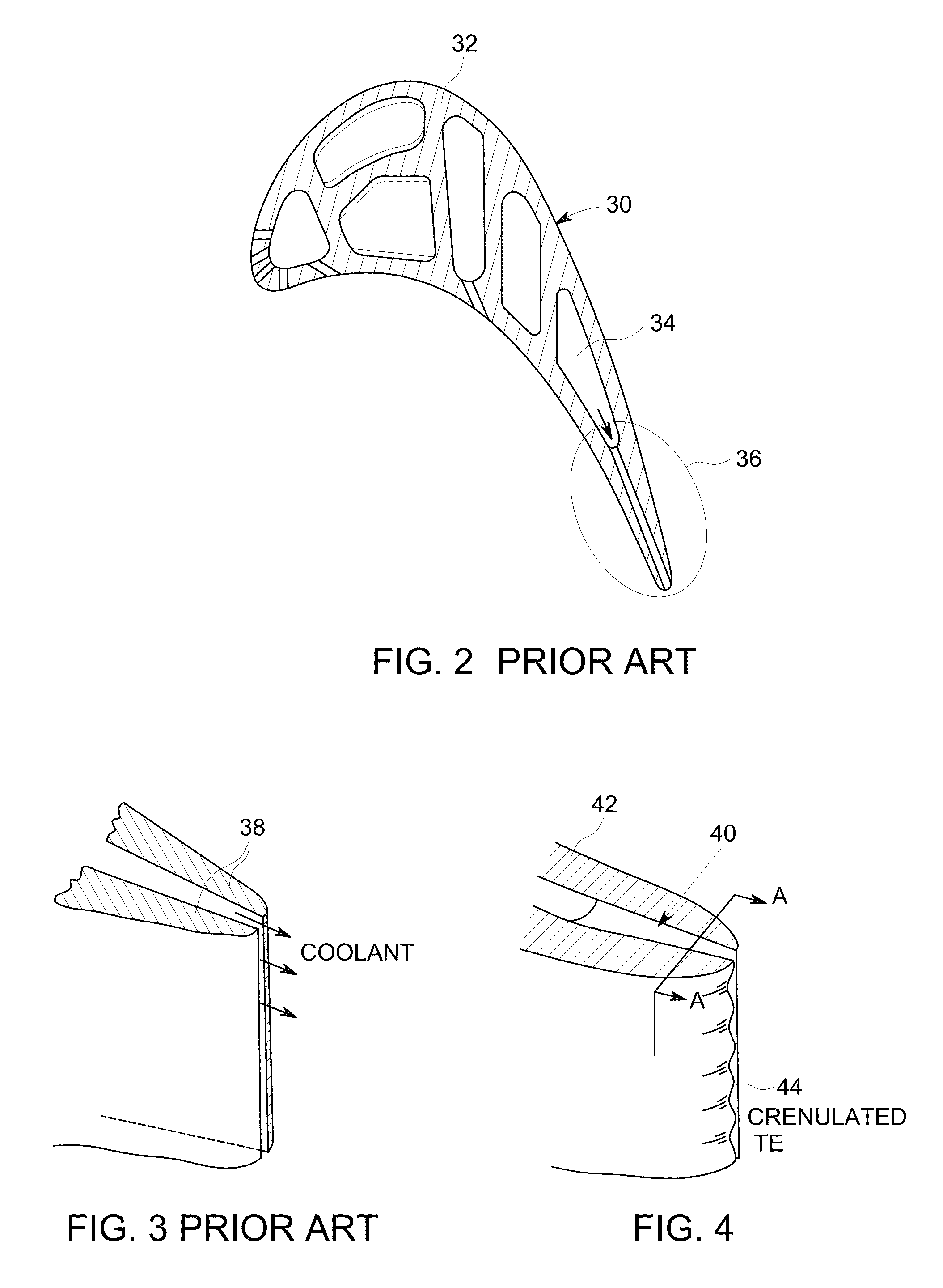
[0038]According to other embodiments such as those depicted in FIGS. 4-8 and 19-20 described in further detail herein, chevron trailing edges are provided on the pressure side, suction side, or both the pressure side and suction side of a high pressure turbine blade or vane to provide a pressure side bleed slot trailing edge wake mixing scheme.

[0039]According to yet other embodiments, fluid injection e...


PUM


Abstract

A high pressure turbine (HPT) blade includes a substantially arcuate trailing edge including one or more fluid injection elements disposed therein. Each fluid injection element injects a fluid such as air into a desired trailing edge region of the HPT blade or vane to enhance mixing out of the wakes generated via the HPT blade or vane. The enhanced mixing out reduces HPT / LPT interaction losses and / or the axial gap between the HPT and LPT components in a gas turbine engine. The interaction losses include unsteady thermal wake segregation effects that lead to unexpected heat-up of endwalls (planforms and blade / vane-tips) of downstream blades / vanes, and further include aerodynamic losses, both transonic and subsonic.

Description

BACKGROUND[0001]The invention relates generally to gas turbine engines and more particularly to a system and method for re-tasking, redesigning and / or manipulating the use of coolant injection holes to enhance the mixing of a gas turbine blade or vane wake to reduce HPT / LPT (high pressure turbine / low pressure turbine) interaction losses and improve the thermal durability of the turbine.[0002]Turbine blade / vane wakes interact with turbine blade / vane shock wave systems and, if not fully mixed, with downstream blades / vanes. This process generates higher losses, and often requires extra axial spacing between the HPT and LPT to fully mix the wakes. Besides the aero-performance benefit of wake mixing, its benefit can also be extended to include the thermal effect. The wakes coming off of the film-cooled turbine vanes and blades have temperature deficits in addition to the pressure deficit. The low-momentum fluid in the wake of an airfoil (vane or blade) migrates downstream, and is ingeste...

Claims


Application Information

Patent Timeline
Patent Type & Authority Patents(United States)
IPC IPC(8): F03B11/00
CPCF01D5/145F01D5/187Y02T50/673Y02T50/671F05D2240/122F05D2240/304F05D2250/184Y02T50/676Y02T50/60
Inventor GUPTA, ANURAGYAO, JIXIAN
Owner GENERAL ELECTRIC CO
Why Eureka
Try Eureka