Method for minimally invasive tendon sheath release

Active Publication Date: 2013-12-17
SONICSURG INNOVATIONS
View PDF25 Cites 25 Cited by
  • Summary
  • Abstract
  • Description
  • Claims
  • Application Information

AI Technical Summary

Benefits of technology

[0009]The long-standing but heretofore unfulfilled need for an improved device and method for minimally invasive tendon sheath release that allows the operation to b

Problems solved by technology

The constant irritation from the tendon repeatedly sliding through the pulley causes the tendon to swell in this area and create the nodule.
Pain usua

Method used


Image

  • Method for minimally invasive tendon sheath release
  • Method for minimally invasive tendon sheath release
  • Method for minimally invasive tendon sheath release

Examples


Embodiment Construction

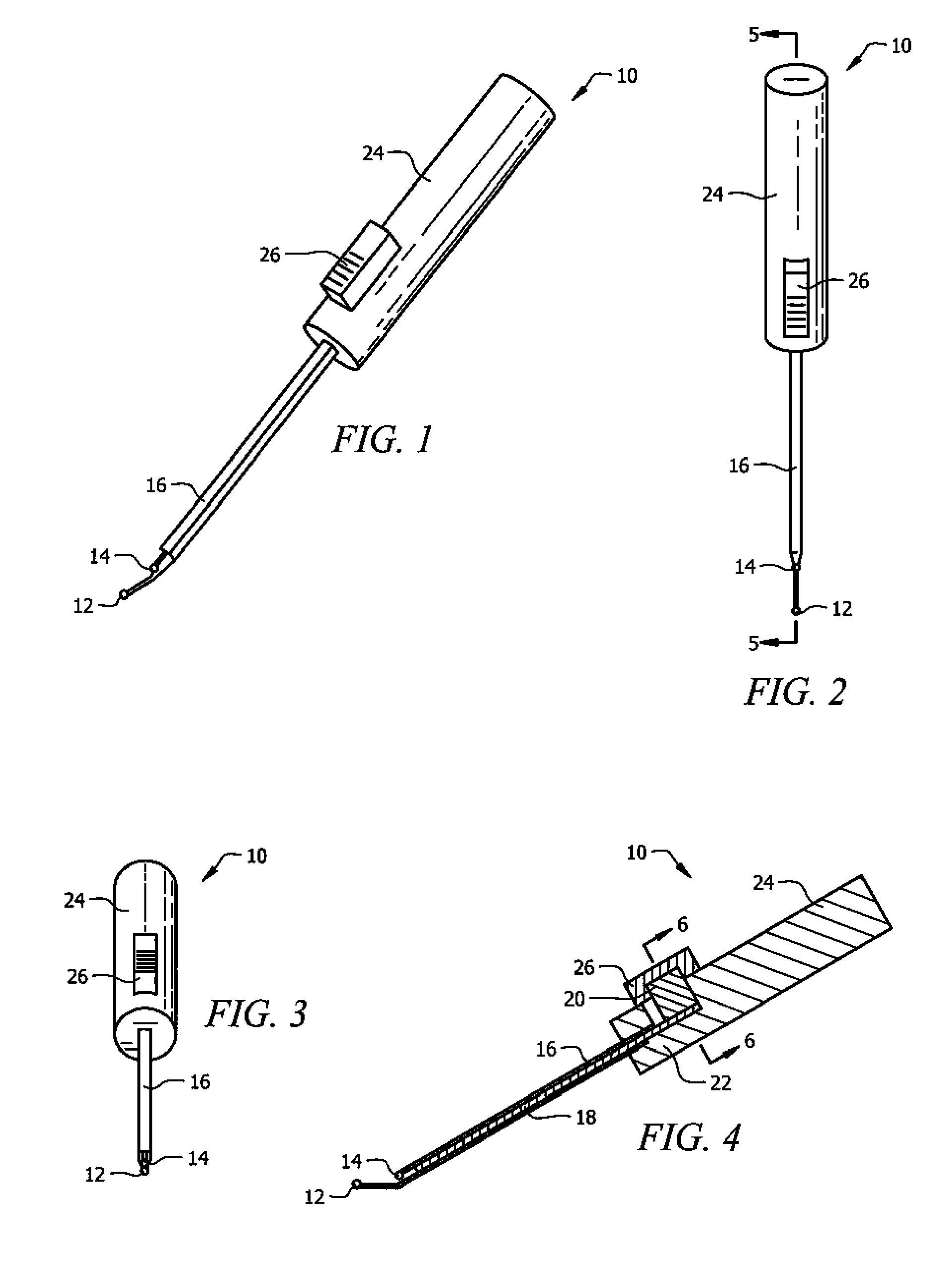
[0046]The following detailed description discloses the preferred dimension of an embodiment and shall be interpreted as illustrative and not in a limiting sense. The device is to be commercially known as the trigger tome.

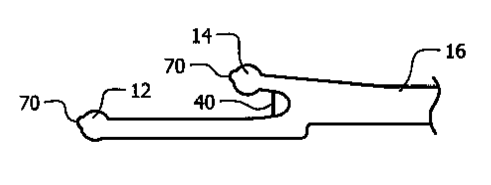
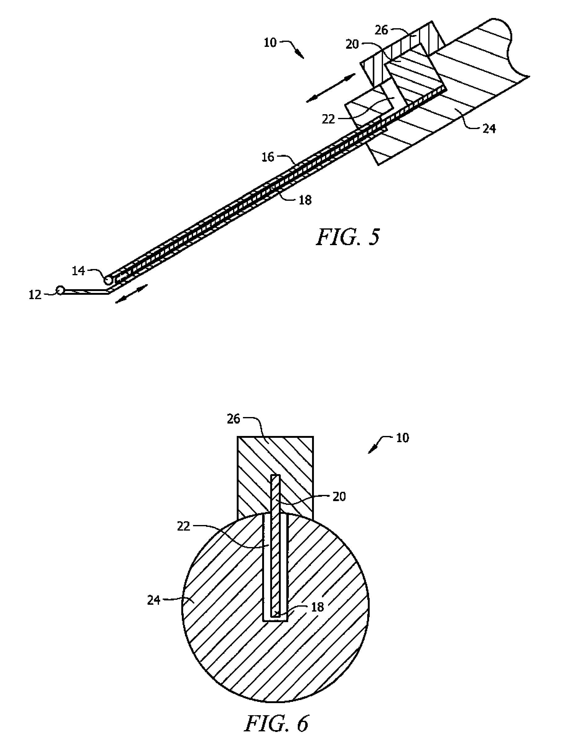
[0047]Ball tipped guide probe 12, as shown in FIGS. 1-5, includes an about 2.5 cm long stainless steel ball tipped probe that tapers from its proximal to distal end, with a proximal round diameter of about 2.5 mm and a distal rounded diameter of about 1.0 mm with an about 3.0 mm diameter ball tip. Ball tipped guide probe 12 is attached to the bottom part of sheath 16. Ball tipped guide probe 12 is curved.

[0048]Dorsal outrigger ball tipped guide 14, as shown in FIGS. 1-5, includes an about 5 mm long by about 1 mm diameter stainless steel ball tip outrigger that extends from the distal top part of sheath 16 and has an about 2 mm diameter ball tip at its terminal end. It may extend at about a 20 to 30 degree angle.

[0049]Sheath 16, as shown in FIGS. 1-3, includes a holl...


PUM


Abstract

A device and method for minimally invasive tendon sheath release. The device and method that enables a surgeon to cut (“open”) a pulley that is obstructing a nodule and keeping a tendon from sliding smoothly. A ball tipped guide probe goes through a small incision and is used to find the edge of the pulley. Once found, the probe is guided to an end of the pulley. After proper position is assured, a cutting blade is deployed by pushing and holding a blade deployment switch. This deploys the sharp end of a retractable cutting shaft beyond the sheath. The entire device is then pushed or pulled using the device handle along the pulley until the pulley is completely released or where resistance is no longer felt. In an alternate embodiment, the cutting blade is static.

Description

CROSS REFERENCE TO RELATED APPLICATION[0001]This application claims priority to U.S. provisional patent application No. 61 / 251,957, entitled “DEVICE FOR MINIMALLY INVASIVE TENDON SHEATH RELEASE,” filed on Oct. 15, 2009 by the same inventor, the contents of which are hereby incorporated by reference.BACKGROUND OF THE INVENTION[0002]1. Field of the Invention[0003]This invention relates to a novel device and method for minimally invasive tendon sheath release. More particularly, it relates to a device and method that allows a surgeon to cut (“open”) a pulley that is obstructing a nodule and keeping a tendon from sliding smoothly.[0004]2. Description of the Prior Art[0005]Tendons that move fingers are held in place on bones by a series of ligaments called pulleys (or sheath). These ligaments form an arch on a bone surface that creates a sort of tunnel through which the tendon extends along the extent of the bone. Triggering is usually the result of a thickening in the tendon that forms ...

Claims


Application Information

Patent Timeline
IPC IPC(8): A61B17/32
CPCA61B17/320036
Inventor JURBALA, BRIAN MICHAEL
Owner SONICSURG INNOVATIONS
Why Eureka
Try Eureka