Wideband balun structure

a wideband balun and structure technology, applied in waveguide type devices, duplex signal operation, pulse techniques, etc., can solve the problems of increasing cost and bulk, reducing flexibility, and prohibitive differential interconnection costs, and achieve the effect of expanding the bandwidth of the wideband balun

Active Publication Date: 2013-12-17
TEKTRONIX INC
View PDF12 Cites 1 Cited by
  • Summary
  • Abstract
  • Description
  • Claims
  • Application Information

AI Technical Summary

Problems solved by technology

However, for interconnect between modules, such as between an active probe and an oscilloscope, the cost of differential interconnects are often prohibitive.
Not only would two coaxial cables be required rather than one (adding cost and bulk, and reducing flexibility), but the two would also need to be tightly matched to prevent mode conversion from differential to common-mode and vice versa.
(Equivalently, for a balun converting a differential input to a single-ended output, half the differential power in the “inverted” input cannot be coupled to the output, and thus is lost.

Method used


Image

  • Wideband balun structure
  • Wideband balun structure
  • Wideband balun structure

Examples


Embodiment Construction

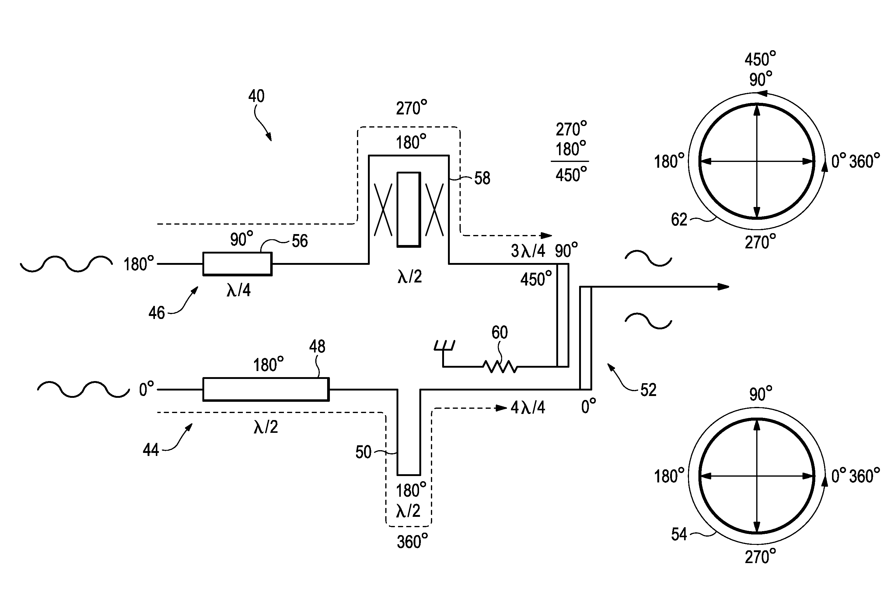
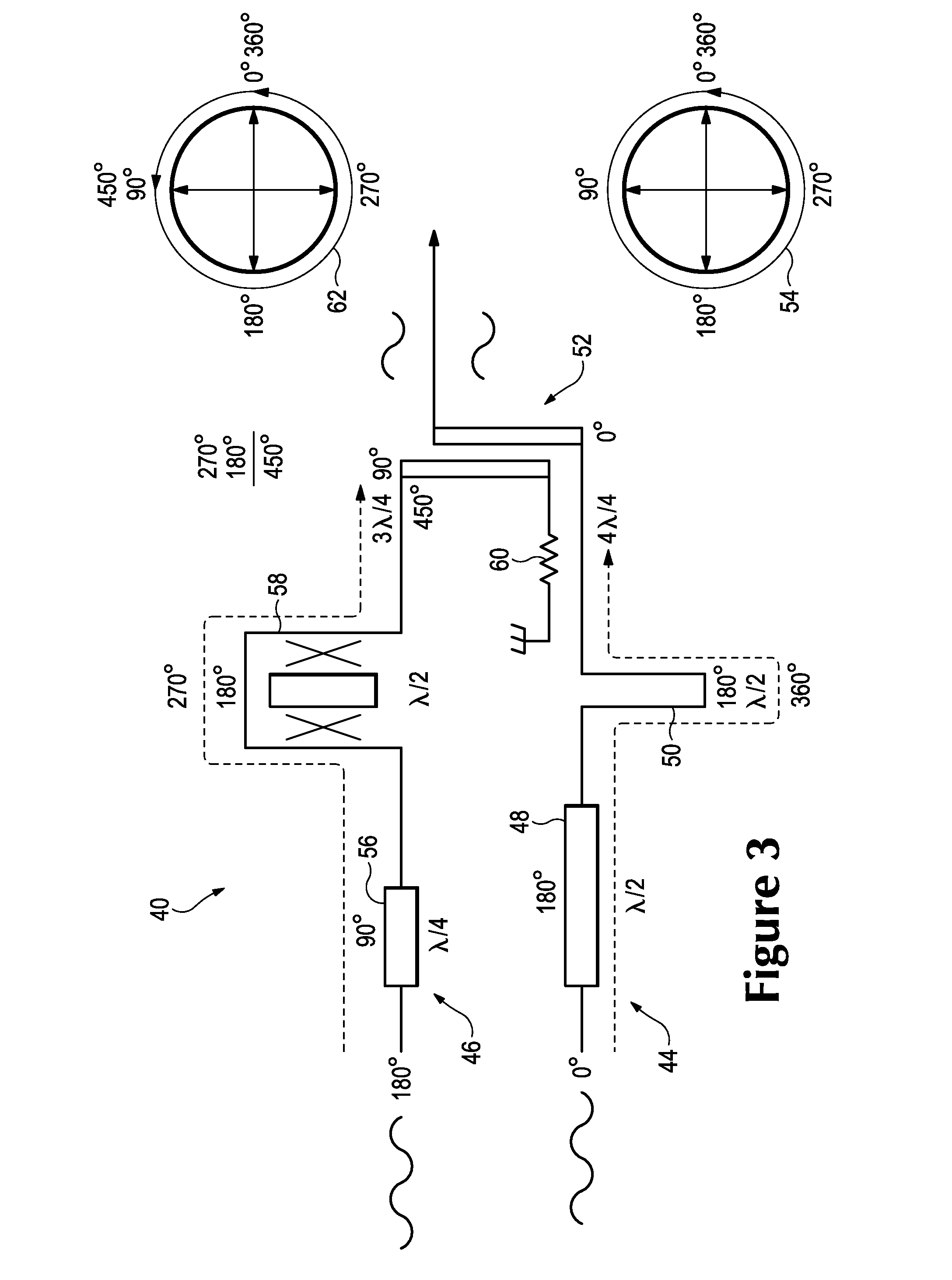
[0016]The wideband balun of the present invention uses phase shifters, phase shapers and a 90° hybrid to phase shift the negative going signal of a differential signal 180° at the output of the 90° degree hybrid. When using 90° hybrid to couple a differential amplifier output through a single-ended cable to a single-ended input or equivalently a single-ended amplifier output through a single-ended cable to a differential input, the 3 dB power loss at DC may be used to compensate for up to 3 dB of cable loss due to high-frequency attenuation in the cable resulting from skin-effect and / or dielectric adsorption. Put another way, the otherwise-wasted high-frequency power may be used in the otherwise-unused output side, coupled through the hybrid, to make up the cable loss, and thus maintain an overall flat response without the additional noise or dynamic range penalties of active cable compensation circuits.

[0017]The phase shift networks consisting of phase shifter and phase shapers may...


PUM


Abstract

A balun structure is disclosed having positive and negative going signal paths coupled to a ninety degree hybrid. The positive signal path has a circuit trace and a phase shaper structure that provides three hundred and sixty degrees of phase shift at Port 1 of the hybrid. The negative going signal path has a circuit trace and a second order phase shaper that provides four hundred and fifty degrees of phase shift at Port 2 of the hybrid. Port 1 is coupled to Port 3 of the hybrid and functions as an output port. The first order phase shaper and the second order phase shaper compensate for the signal loss caused by a signal cable coupled to the output port and provide a frequency band from DC to at least 15 GHz and a transient response having less than ten percent pre-shoot.

Description

CROSS-REFERENCE TO RELATED APPLICATIONS[0001]This application claims the benefit of priority of U.S. Provisional Application No. 61 / 509,365, filed Jul. 19, 2011 and incorporates by reference herein the contents of U.S. Provisional Application No. 61 / 509,365 as if such contents were set forth in full herein.BACKGROUND OF THE INVENTION[0002]Broadband DC-coupled amplifiers are generally designed with differential inputs and outputs for reasons such as power supply (and other common-mode) noise immunity, cancelation of even-order harmonic distortion, cancelation of DC offset terms, increased dynamic range due to swing on both outputs, etc. For interconnect between amplifiers on one die, one package, or even on one circuit board, the expense of the differential interconnect is small compared to the advantages of differential design. However, for interconnect between modules, such as between an active probe and an oscilloscope, the cost of differential interconnects are often prohibitive....

Claims


Application Information

Patent Timeline
Patent Type & Authority Patents(United States)
IPC IPC(8): H04B3/00
CPCH01P1/184H01P5/10
Inventor KNIERIM, DANIEL G.LAMB, JAMES S.BARTLETT, JOSIAH A.
Owner TEKTRONIX INC
Why Eureka
Try Eureka