Medical pump monitoring system

a technology of pump monitoring and monitor system, which is applied in the direction of process and machine control, instruments, data processing applications, etc., can solve the problems of difficult to accurately ascertain the difficult to identify the points of the patient into which the medical fluid is injected, and complicated administration methods, etc., to achieve the effect of easy to confirm the current state of infusion lines

Active Publication Date: 2013-12-17
TERUMO KK
View PDF23 Cites 14 Cited by
  • Summary
  • Abstract
  • Description
  • Claims
  • Application Information

AI Technical Summary

Benefits of technology

[0017]The present invention has been made in the light of problems as described above, and its object is to provide a system in which the operation conditions of a plurality of medical pumps are monitored for one patient with a function of creat

Problems solved by technology

Varieties of therapies and drugs for use in those therapies have emerged and administration methods have become complicated due to recent advancement of medical treatments.
It is important in safe administration that the state of the infusion line is ascertained correctly, and there are various patterns as to states of infusion lines as administration passes to the patient in this way, but in fact, it becomes very difficult to identify the points of the patient into which the medical fluid is injected if infusion lines running from a plurality of pumps are connected with one another and cross one another.
However, conventional pump monitor systems have no functions to display infusion lines on the system, thus m

Method used


Image

  • Medical pump monitoring system
  • Medical pump monitoring system
  • Medical pump monitoring system

Examples


first embodiment

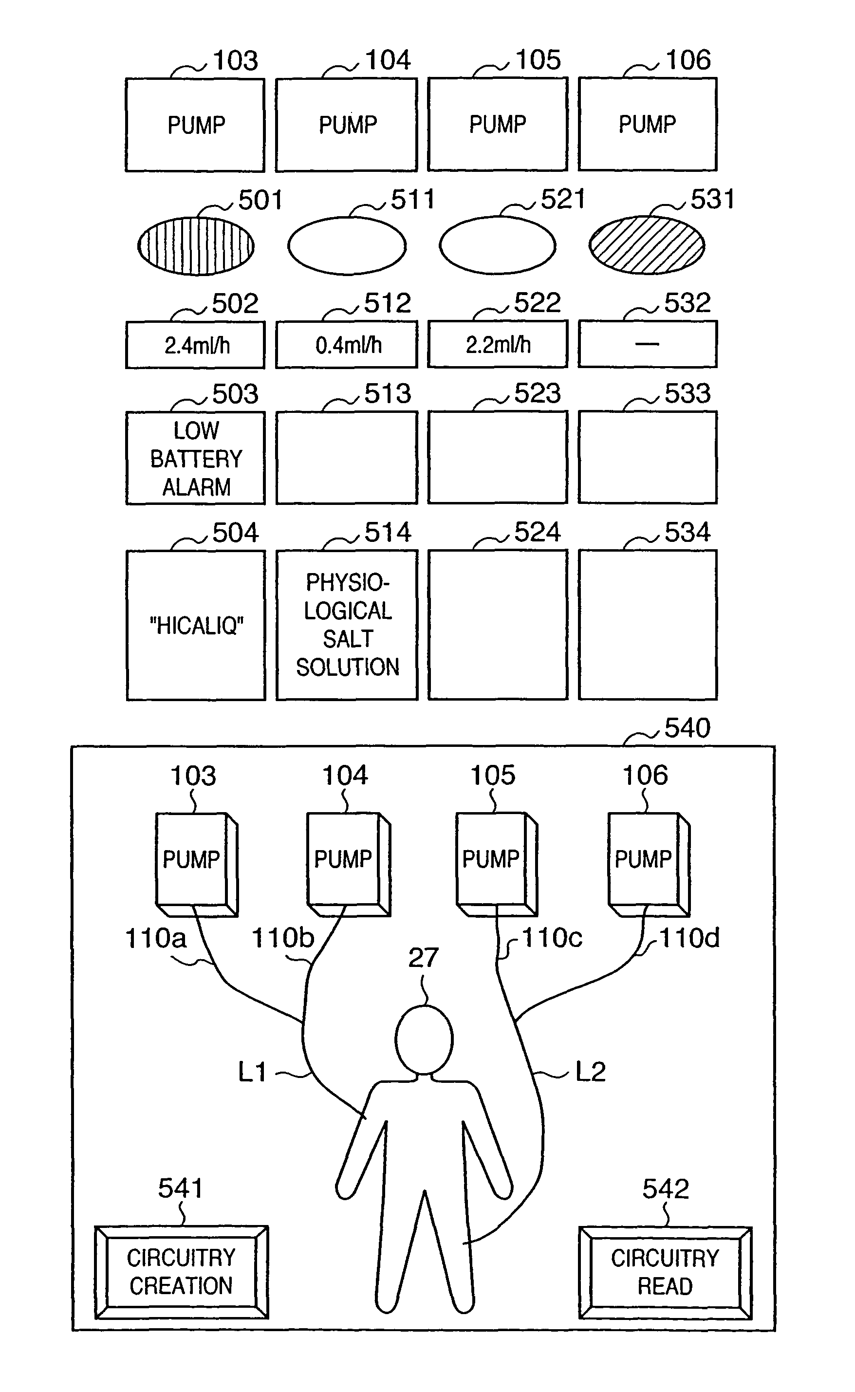
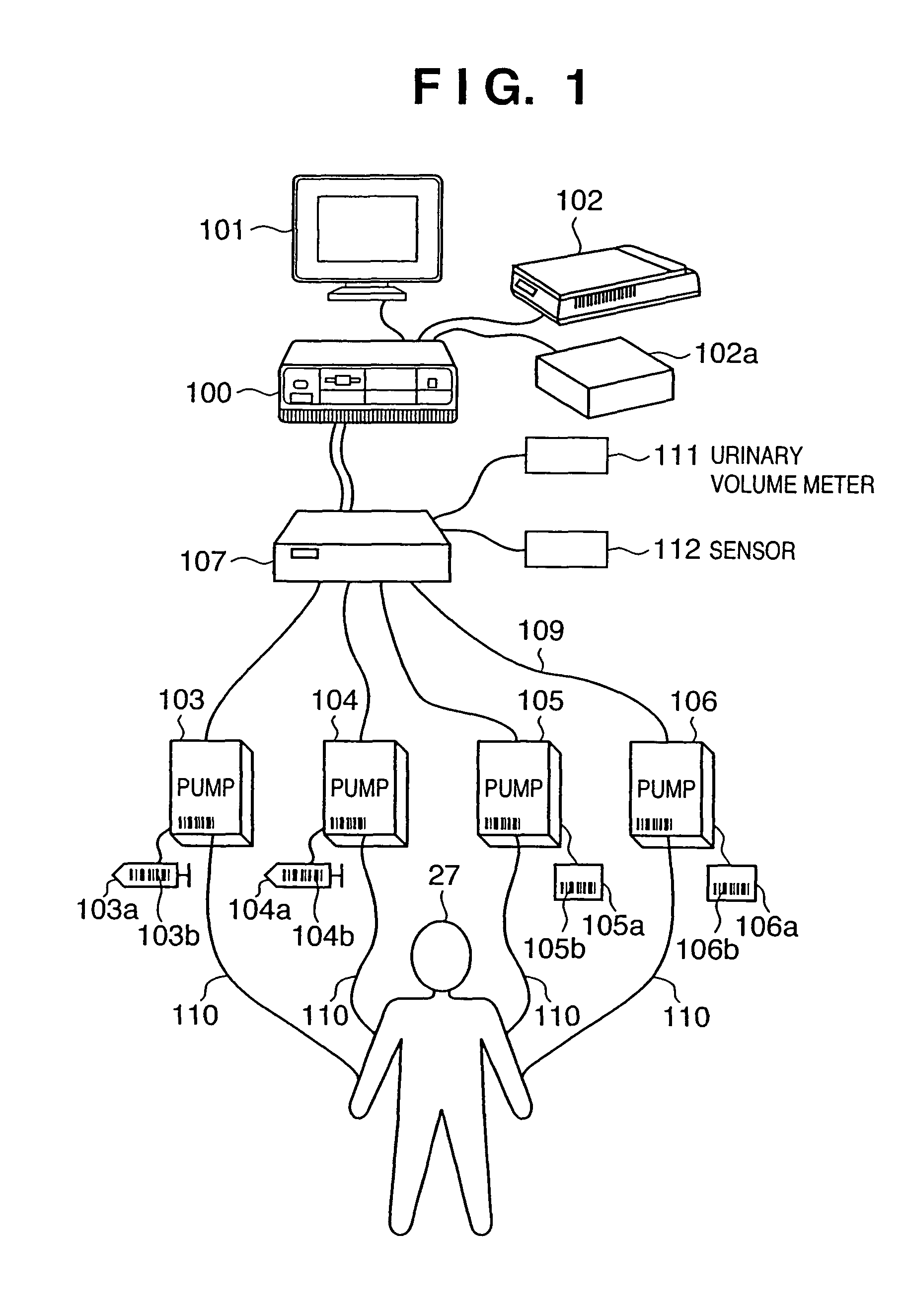
[0053]Examples of specific embodiments of the present invention will be described below. A block diagram of a medical pump system of the present invention is shown in FIG. 1. In this embodiment, an example of collecting and managing information of four medical pumps is described.

[0054]Reference numeral 100 denotes a controller (control unit), which makes up a central portion of this medical pump monitor system, and for the controller, a personal computer having an inputting device such as a keyboard and a pointing device such as a mouse is usually used. Reference numeral 101 denotes a display (display unit), which displays flow values and alarm information for a plurality of medical pumps of 103, 104, 105 and 106, collected by the controller 100, and the urinary volume from urinary volume meters 111 and the amount of electrolytes (Na+, Ca2+, K+, Cl−) from catheter type censor 112, and displays infusion lines.

[0055]In the case where the personal computer is used as the controller 100...

second embodiment

[0092]The real-time monitoring system of the present invention will be described in detail below, using the drawings. FIG. 11 is a block diagram of the present invention. In FIG. 11, an example of connection of three external apparatuses including medical devises and the like such as infusion pumps, syringe pumps, body pressure monitors, body temperature monitors, urinary volume monitors and electrocardiographs is shown, but this number of apparatuses can be arbitrarily increased or decreased. An external apparatus 1 (1121) is connected through a communication cable to a communication port (external communication unit) 1 (1111) of this system (1105). In a similar way, an external apparatus 2 (1122) and an external apparatus 3 (1123) are connected to a communication port (external communication unit) 2 (1112) and a communication port (external communication unit) 3 (1113), respectively, in a one-to-one correspondence.

[0093]Communication ports 1(1111), 2(1112) and 3(1113) are brought ...


PUM


Abstract

A medical pump monitor system in which an infusion circuitry creation unit setting/changing the connection conditions of infusion lines from a plurality of medical pumps, and administration passes and/or administration positions for a patient is provided, and it is made possible to display infusion circuitry data created in the infusion circuitry creation unit on a monitor screen by operations by an operator of the medical pump monitor system. And, a real-time monitoring system performing real time communication with external apparatuses including one or more medical apparatuses, and controlling the external apparatuses and/or displaying the conditions of the external apparatuses, including a communication unit communicating with external apparatuses, a display unit displaying the conditions of the external apparatuses, storing unit storing one or more past communication data obtained by the communication unit, a comparison unit comparing currently communicated data with past data, and a control unit controlling contents to be displayed on the display unit based on signals from the comparison unit, in which the comparison unit reduces the amount of the data for the amount of signals to be sent to the control unit, in the case where the past data and the current data are identical to each other in comparison with the case where the past data and the current data are different from each other.

Description

FIELD OF THE INVENTION[0001]The present invention relates to a medical pump monitor system administering medical fluids using a plurality of medical pumps for one patient, and managing information of these medical pumps collectively, a controlling method therefore, and a computer-readable memory associated with control thereof. The present invention also relates to a real-time monitoring system performing real-time communication with external apparatuses including one or more medical apparatuses to control such external apparatuses and / or display the conditions thereof, a controlling method therefore, and a computer-readable memory (storage medium) storing therein a control program thereof.BACKGROUND OF THE INVENTION[0002]Varieties of therapies and drugs for use in those therapies have emerged and administration methods have become complicated due to recent advancement of medical treatments. Accordingly, therapies in which a plurality of medical pumps (syringe pump and infusion pump...

Claims


Application Information

Patent Timeline
IPC IPC(8): G06Q50/00A61M5/14A61M5/142A61M5/172
CPCA61M5/1413A61M5/142A61M5/172A61M2205/3331G16H20/17
Inventor ZAITSU, AKINORIISHIKAWA, KOUNAKAHARA, KENJI
Owner TERUMO KK
Why Eureka
Try Eureka