Downhole steam generator and method of use

a technology of steam generator and downhole, which is applied in the direction of borehole/well accessories, combustion types, insulation, etc., can solve the problems of inability to inject steam, difficulty and cost in recovering hydrocarbons, and inability to stabilize wellbores

Active Publication Date: 2013-12-24
WORLD ENERGY SYST
View PDF79 Cites 10 Cited by
  • Summary
  • Abstract
  • Description
  • Claims
  • Application Information

AI Technical Summary

Benefits of technology

[0010]Embodiments of the invention relate to downhole steam generator systems. In one embodiment, a downhole steam generator (DHSG) includes a burner head, a combustion sleeve, a vaporization sleeve, and a support / protection sleeve. The burner head may have a sudden expansion region with one or more injectors. The combustion sleeve may be a water-cooled liner having one or more water injection arrangements. The DHSG may be configured to acoustically isolate the various fluid flow streams that are directed to the DHSG. The components of the DHSG may be optimized to assist in the recovery of hydrocarbons from different types of reservoirs.

Problems solved by technology

The high viscosity makes it difficult and expensive to recover the hydrocarbon.
Steam cannot be injected though these layers because the heat could potentially expand the permafrost, causing wellbore stability issues and significant environmental problems with melting permafrost.
Additionally, the current methods of producing heavy oil reservoirs face other limitations.
One such problem is wellbore heat loss of the steam, as the steam travels from the surface to the reservoir.
This problem is worsened as the depth of the reservoir increases.
This situation lowers the energy efficiency of the oil recovery process.
DHSGs, however, also present numerous challenges, including excessive temperatures, corrosion issues, and combustion instabilities.
These challenges often result in material failures and thermal instabilities and inefficiencies.

Method used


Image

  • Downhole steam generator and method of use
  • Downhole steam generator and method of use
  • Downhole steam generator and method of use

Examples


Embodiment Construction

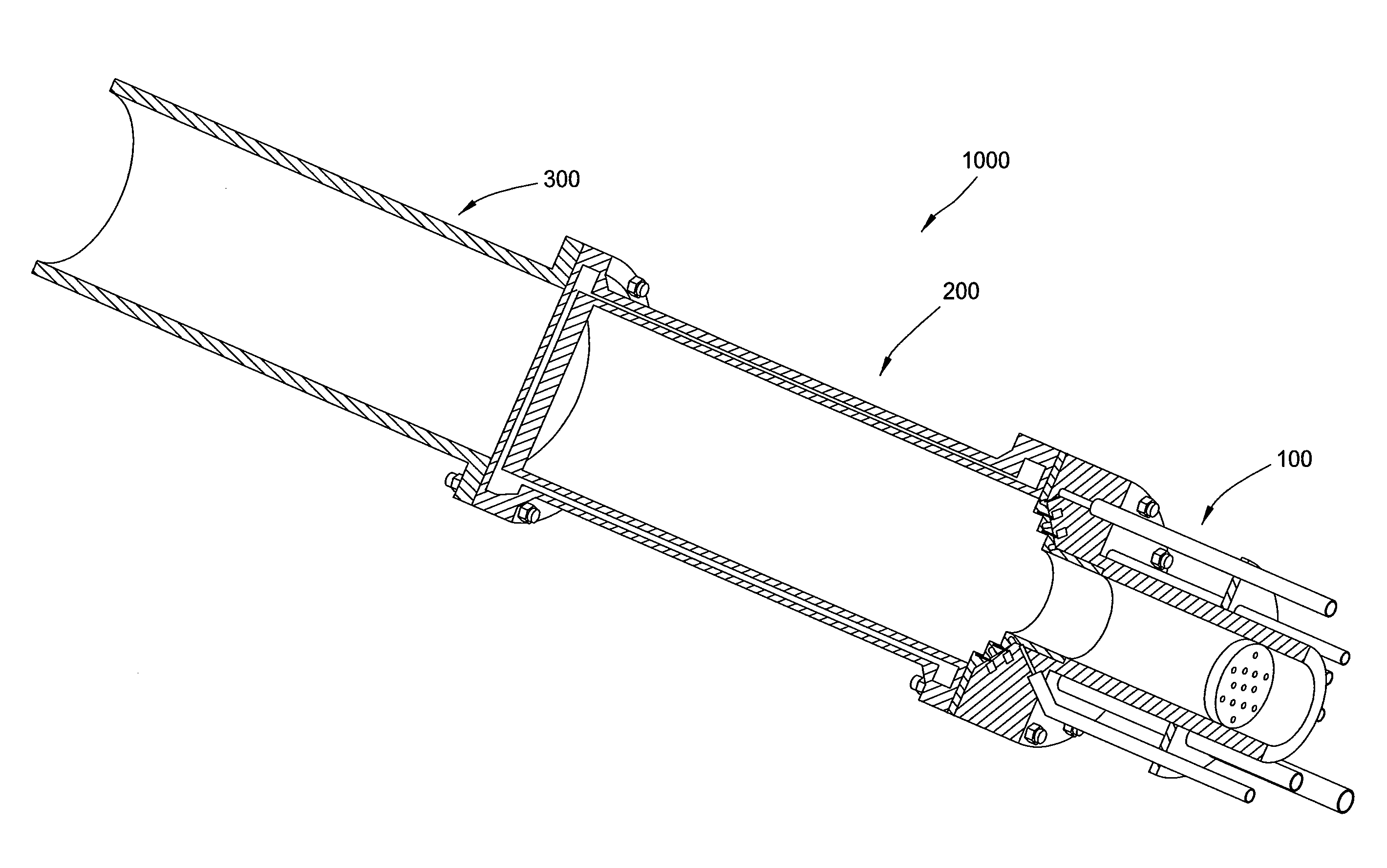
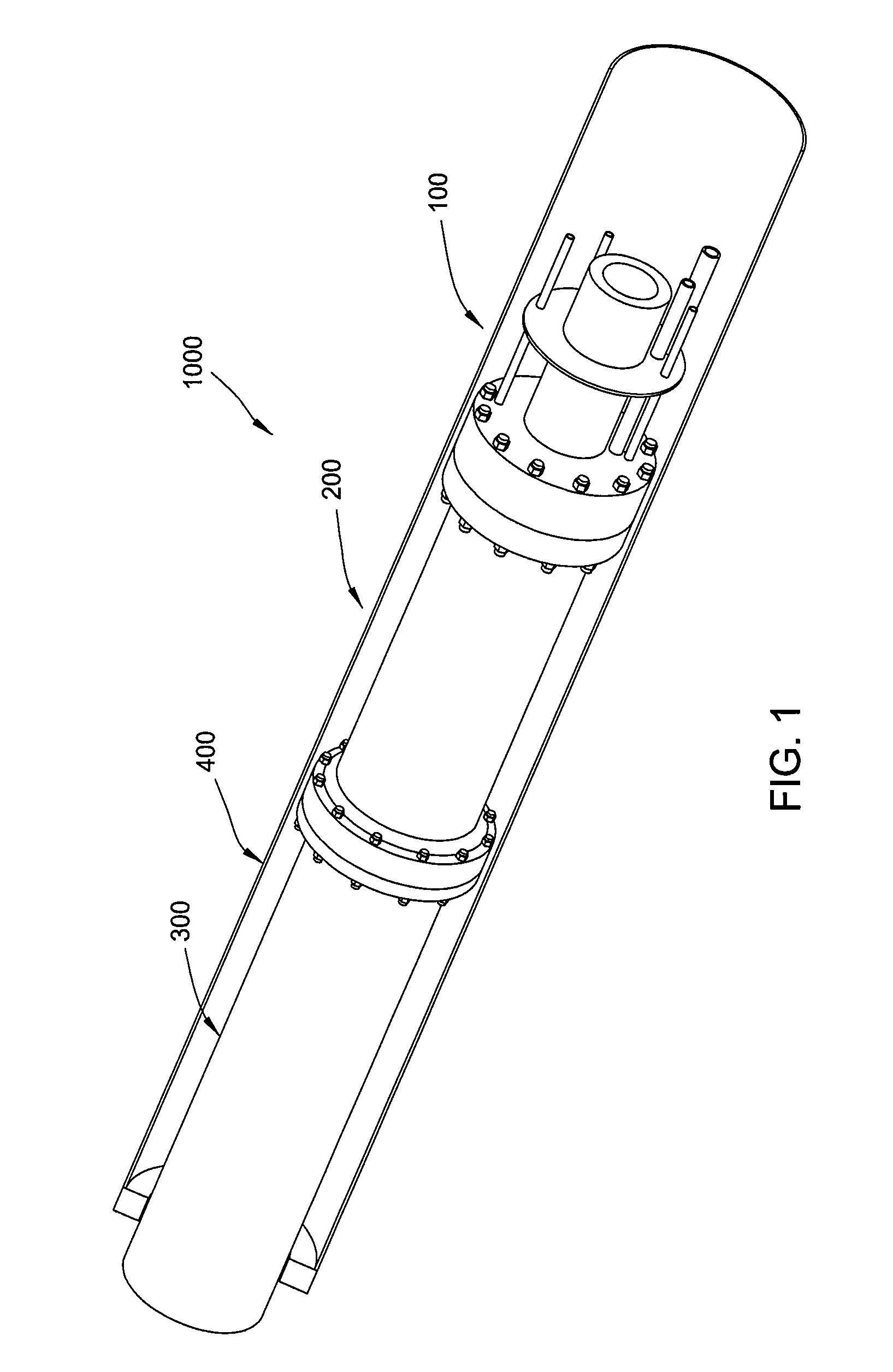
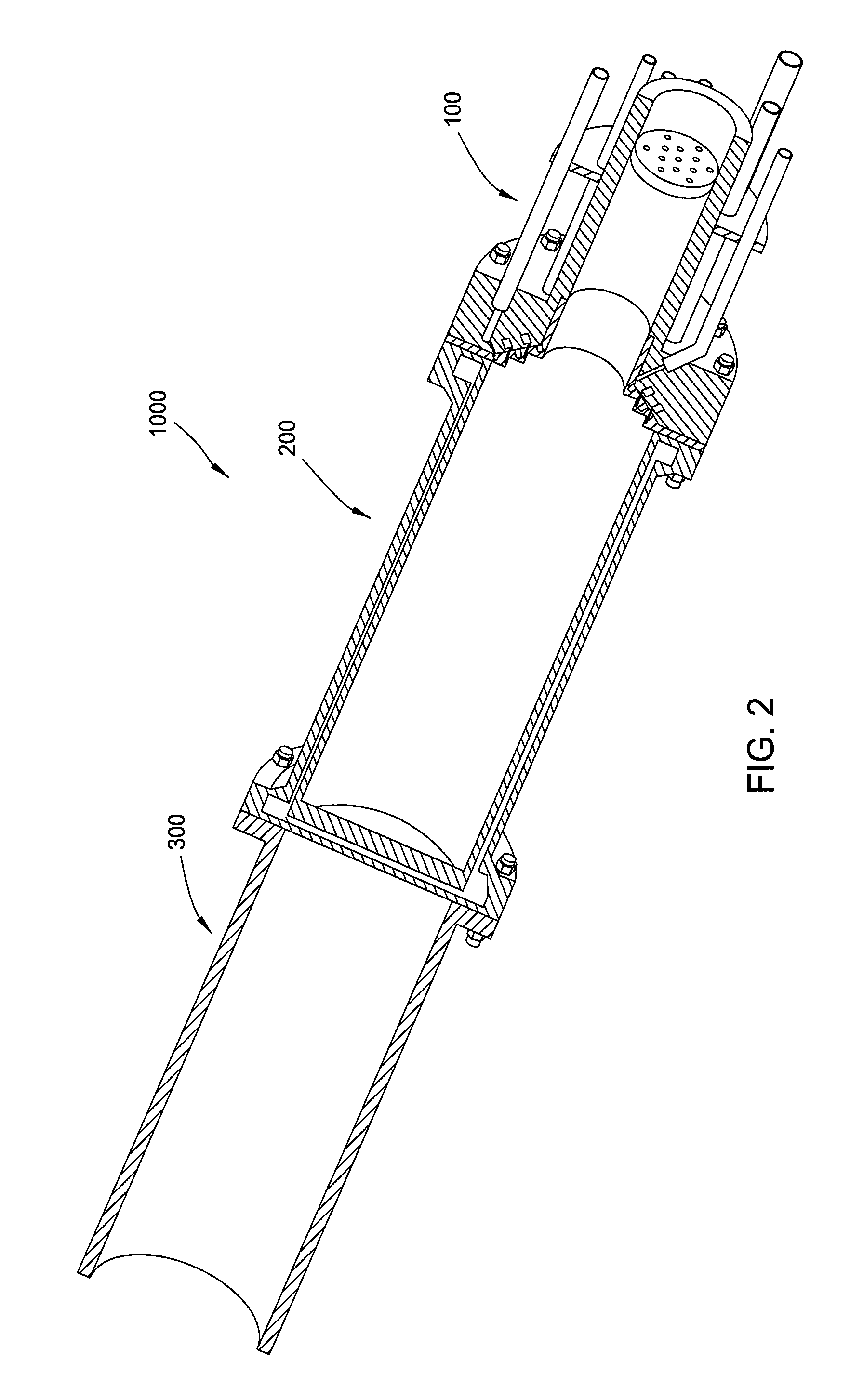
[0020]FIGS. 1 and 2 illustrate a downhole steam generation system 1000. Although described herein as a “steam” generation system, the system 1000 may be used to generate any type heated liquid, gas, or liquid-gas mixture. The system 1000 includes a burner head assembly 100, a liner assembly 200, a vaporization sleeve 300, and a support sleeve 400. Burner head assembly 100 is coupled to the upper end of liner assembly 200, and the vaporization sleeve 300 is coupled to the lower end of liner assembly 200. The support sleeve 400 is coupled to the vaporization sleeve 300 and may be operable to support and lower the system 1000 into a wellbore on a work string. The components may be coupled together by a bolt and flange connection, a threaded connection, a welded connection, or other connection mechanisms known in the art. One or more fuels, oxidants, coolants, diluents, solvents, and combinations thereof may be supplied to the system 1000 to generate a fluid mixture for injection into o...


PUM


Abstract

A downhole steam generation system may include a burner head assembly, a liner assembly, a vaporization sleeve, and a support sleeve. The burner head assembly may include a sudden expansion region with one or more injectors. The liner assembly may include a water-cooled body having one or more water injection arrangements. The system may be optimized to assist in the recovery of hydrocarbons from different types of reservoirs. A method of recovering hydrocarbons may include supplying one or more fluids to the system, combusting a fuel and an oxidant to generate a combustion product, injecting a fluid into the combustion product to generate an exhaust gas, injecting the exhaust gas into a reservoir, and recovering hydrocarbons from the reservoir.

Description

CROSS REFERENCE TO RELATED APPLICATIONS[0001]This application claims benefit of U.S. Provisional Patent Application Ser. No. 61 / 311,619, filed Mar. 8, 2010, and U.S. Provisional Patent Application Ser. No. 61 / 436,472, filed Jan. 26, 2011, each of which are herein incorporated by reference in their entirety.BACKGROUND OF THE INVENTION[0002]1. Field of the Invention[0003]Embodiments of the inventions relate to downhole steam generators.[0004]2. Description of the Related Art[0005]There are extensive viscous hydrocarbon reservoirs throughout the world. These reservoirs contain a very viscous hydrocarbon, often called “bitumen,”“tar,”“heavy oil,” or “ultra heavy oil,” (collectively referred to herein as “heavy oil”) which typically has viscosities in the range from 100 to over 1,000,000 centipoise. The high viscosity makes it difficult and expensive to recover the hydrocarbon.[0006]Each oil reservoir is unique and responds differently to the variety of methods employed to recover the hy...

Claims


Application Information

Patent Timeline
Patent Type & Authority Patents(United States)
IPC IPC(8): E21B43/243E21B36/02
CPCE21B36/02E21B43/2406F22B1/22F22B1/26E21B43/243F23D14/22
Inventor CASTROGIOVANNI, ANTHONY GUSVOLAND, RANDALL TODDWARE, CHARLES H.FOLSOM, BLAIR A.JOHNSON, M. CULLEN
Owner WORLD ENERGY SYST
Why Eureka
Try Eureka