Upper vehicle-body structure of vehicle

a vehicle body and upper body technology, applied in the direction of roofs, vehicular safety arrangments, pedestrian/occupant safety arrangements, etc., can solve the problems of not being able to ensure the stability of curtain airbag inflation for both passengers seated in the front seat and the passenger seated in the rear seat, and the difference in gas supply time between the supply of front-seat airbag and the supply of rear-seat airbag, etc., to achieve the effect of stable airbag inflation

Inactive Publication Date: 2013-12-24
MAZDA MOTOR CORP
View PDF10 Cites 6 Cited by
  • Summary
  • Abstract
  • Description
  • Claims
  • Application Information

AI Technical Summary

Benefits of technology

[0009]An object of the present invention is to provide an upper vehicle-body structure of a vehicle which can ensure the stable inflation of the airbag for the both passengers seated in the front and rear seats, arranging the roof reinforcing member in back of the pillars with an offset distance.
[0011]According to the present invention, since at least a portion of the inflator overlaps with the roof reinforcing member in the vehicle longitudinal direction, the inflator can be arranged properly close to the position right above the center pillar which may be the best position for the stable inflation of the airbag, thereby ensuring the stable inflation of the airbag for the both passengers seated in the front and rear seats. Further, since the depth of the part of the concave portion overlapping with the inflator is shallower than that of the other part of the concave portion positioned nearer the pillars than the part of the concave portion overlapping with the inflator is, even in the structure in which the roof reinforcing member is arranged in back of the pillars with such an offset distance, the vertical width of the roof side rail can be made smaller, keeping the appropriate installation of the airbag to the vehicle body.
[0012]According to an embodiment of the present invention, the roof reinforcing member is arranged in back of the pillars with an offset distance and further includes a slant portion which is formed at an end portion of the roof reinforcing member and slants outward and downward, the concave portion is provided to extend inward, in the vehicle width direction, from the end portion of the roof reinforcing member, and the concave portion is comprised of plural concave portions which are arranged away from each other in the vehicle longitudinal direction, a foremost concave portion of which is configured such that an outside end portion thereof approaches gradually closer to the pillars along the slant portion, a rearmost concave portion of which is configured such that an outside end portion thereof goes rearward gradually further away from the foremost concave portion and the depth thereof is shallower than that of the foremost concave portion. Thereby, since the plural concave portions are provided and the distance between the foremost concave portion and the rearmost concave portion is configured to increase gradually toward the outside in the vehicle width direction, a connection portion of the roof reinforcing member and the roof side rail is hardened, so that the load acting on the pillar can be efficiently transmitted to the roof reinforcing member via the roof side rail. Further, since the depth of the rearmost concave portion is shallower than that of the foremost concave portion, any interference of the rearmost concave portion with the inflator can be prevented.
[0013]According to another embodiment of the present invention, outside end portions, in the vehicle width direction, of the concave portion and inside end portions, in the vehicle width direction, of the roof side rails are arranged to face to each other and away from each other. Thereby, an impact load acting on the pillars can be absorbed by the portion of the roof reinforcing member away from the roof side rail at the vehicle side collision, and after the roof side rail contacts the roof reinforcing member, the impact load can be transmitted to another vehicle-body forming member via the roof reinforcing member. Accordingly, both the impact absorption and the impact transmission can be properly achieved, preventing any interference with the inflator.
[0014]According to another embodiment of the present invention, a sunroof is provided at a roof of the vehicle, a peripheral-frame reinforcing member to reinforce a connection portion of the roof reinforcing member to the pillars is provided at a peripheral frame of the sunroof, and the peripheral-frame reinforcing member and the concave portion of the roof reinforcing member form together a closed cross section. Thereby, the connection of the pillars and the roof reinforcing member can be strengthened by utilizing the peripheral-frame reinforcing member, so that the impact load acting on the pillars can be efficiently transmitted to the roof reinforcing member via the roof side rails.
[0015]According to another embodiment of the present invention, an assist-grip attachment seat portion which projects toward the inside of a vehicle compartment is provided at an inside portion, in the vehicle width direction, of a specified portion of the roof side rail which is located further away from the pillar than the roof reinforcing member in the vehicle longitudinal direction, the inflator and the airbag are arranged above and below the assist-grip attachment seat portion, respectively, the inflator is arranged such that a portion thereof positioned nearer the pillar approaches closer to a lower edge portion of the roof side rail, and the airbag comprises a connection portion which is coupled to an end portion of the inflator positioned on the side of the pillar. Thereby, the inflator and the airbag can be arranged compactly, avoiding a position of the assist-grip attachment seat portion properly.

Problems solved by technology

However, since the inflator is arranged below the center frame, i.e., in a storage recess portion which is formed at the roof side rail in the above-described first patent document, it is necessary that the roof side rail ensures an arrangement space by arranging the inflator and the center frame in a vertical direction, so that it may not be easy to make the vertical width of the roof side rail properly small, keeping an appropriate installation of the curtain airbag to a vehicle body.
However, in a case in which the arrangement position of the inflator is offset longitudinally from the longitudinally-central position of the curtain airbag configured to be used in common as a front-seat airbag and a rear-seat airbag, there occurs a difference in the gas-supply time between the supply to the front-seat airbag and the supply to the rear-seat airbag.
Accordingly, the expansion characteristics of the front-seat airbag becomes different from those of the rear-seat airbag, so that there is a concern that the stable inflation of the curtain airbag for both a passenger seated in the front seat and a passenger seated in the rear seat may not be ensured.
Accordingly, the inflator is offset further rearward from the longitudinally-central position of the curtain airbag, so that there is a concern that the offset amount of the possible arrangement position of the inflator from the best arrangement position (around the position right above the center pillar) of the inflator for its stable inflation may be improperly large.

Method used


Image

  • Upper vehicle-body structure of vehicle
  • Upper vehicle-body structure of vehicle
  • Upper vehicle-body structure of vehicle

Examples


embodiment 1

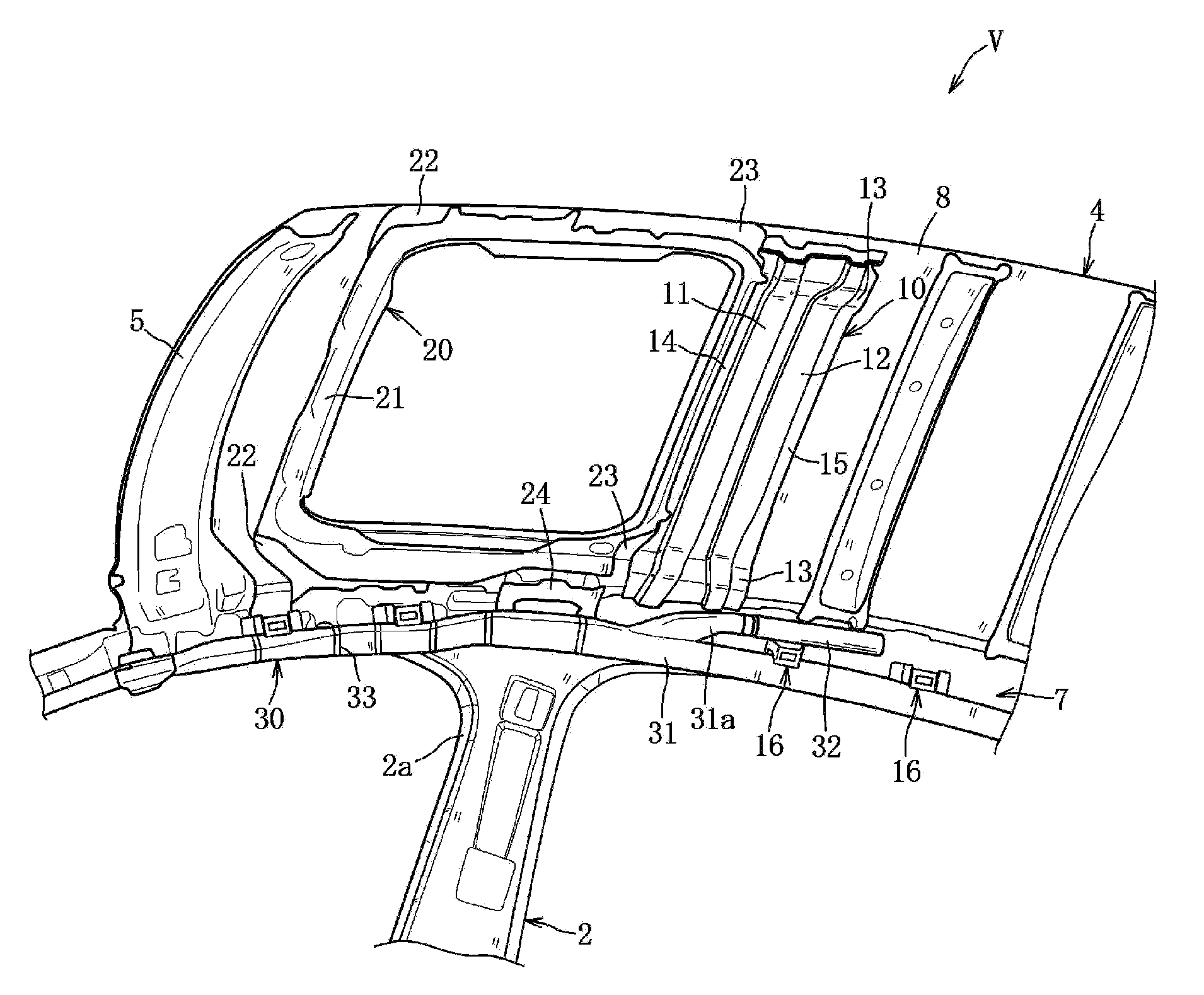
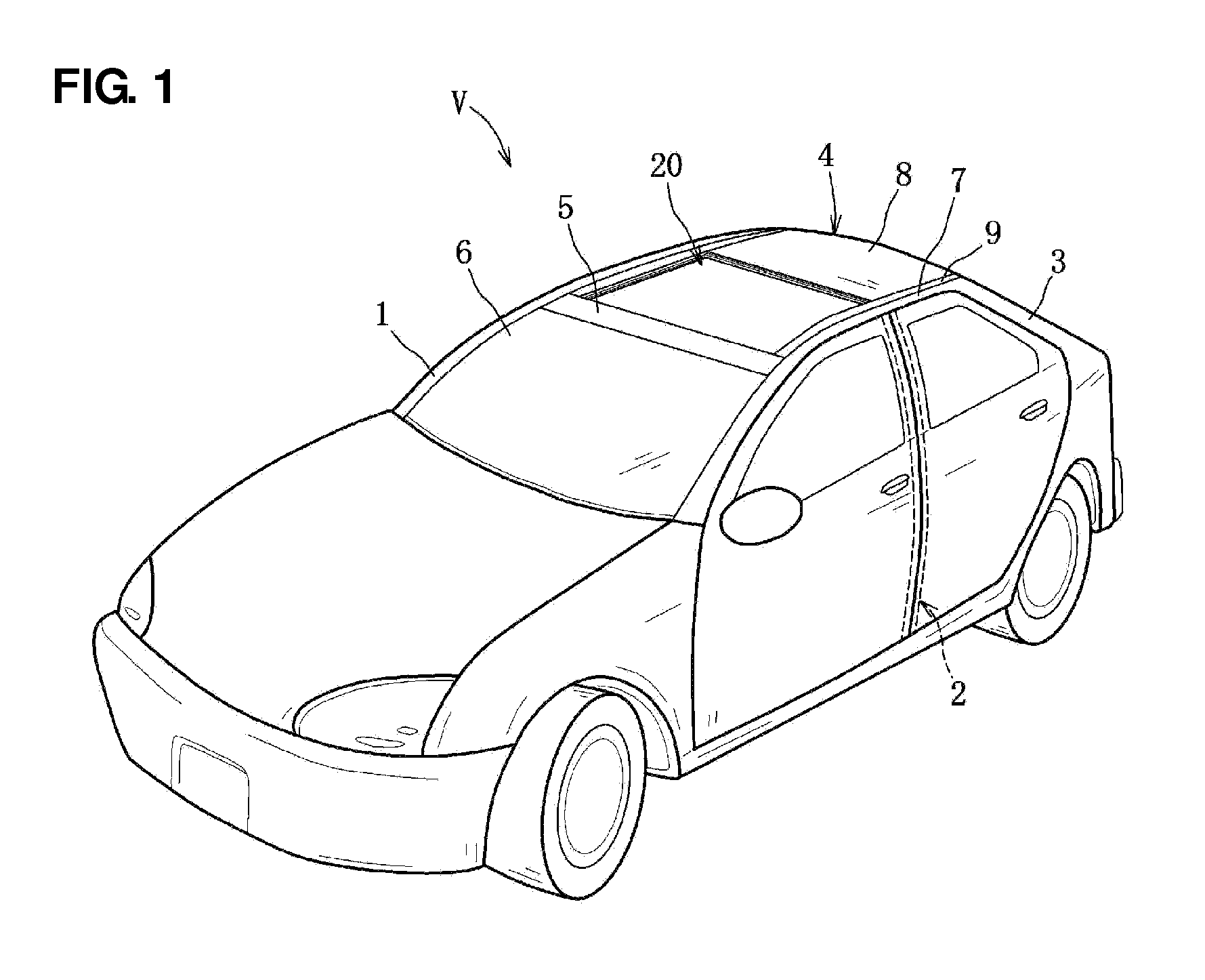
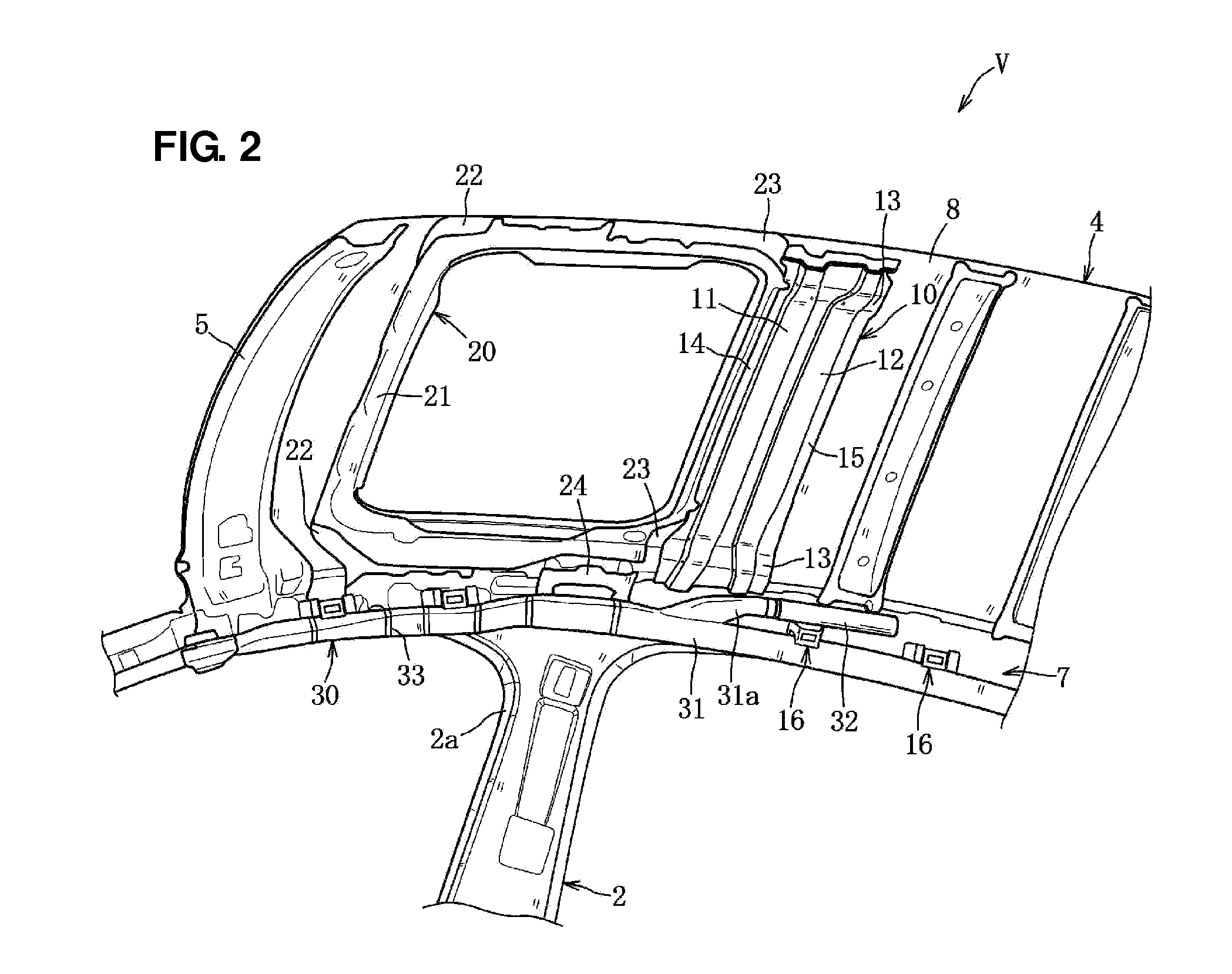
[0030]A first embodiment of the present invention will be described referring to FIGS. 1 through 10. As shown in FIGS. 1 and 2, a vehicle V of the present embodiment comprises a pair of right-and-left front pillars 1, a pair of right-and-left center pillars 2, a pair of right-and-left rear pillars 3, a roof 4 which is equipped with a sunroof unit 20 at its front-side portion, a pair of right-and-left curtain airbag unit 30, and others. As shown in FIG. 1, a front header 5 which extends in a vehicle width direction is provided at an upper end portion of the pair of front pillars 1, to which an upper portion of a windshield (front window glass) 6 is attached.

[0031]As shown in FIGS. 1 and 2, the pair of center pillars 2 is provided at a central position between a frond seat (not illustrated) and a rear seat (not illustrated). As shown in FIG. 6, the right-side center pillar 2 has a closed cross section extending vertically which is formed by a center pillar outer 2a and a center pillar...

embodiment 2

[0056]Next, an upper vehicle-body structure of the vehicle V according to a second embodiment 2 will be described referring to FIG. 11. Only structures of the second embodiment which are different from the above-described first embodiment will be described. The same references are used to denote the same members as the first embodiment, and descriptions of those are omitted.

[0057]A roof reinforcement 10A is arranged in back of the pair of center pillars 2 with an offset distance, and includes a wedge-shaped concave portion 17 which has a wedge-shaped section extending over a vehicle-width-direction whole width. The wedge-shaped concave portion 17 is configured such that its bottom portion slants obliquely rearward and upward, that is—its rear depth is becomes shallower. A front flange 14A and a rear flange 15A are provided at a front end portion and a rear end portion of the wedge-shaped concave portion 17, and joined to a back face of the rear peripheral-frame reinforcing member 23...


PUM


Abstract

A pair of right-and-left center pillars, a pair of right-and-left roof side rails, and an inflator provided on the inside, in a vehicle width direction, of the roof side rails and capable of supplying a gas pressure to an airbag are provided. A roof reinforcing member which extends in the vehicle width direction over respective upper end portions of the center pillars or respective nearby portions to upper ends of the center pillars is provided, which includes a front concave portion and a rear concave portion which are concaved downward respectively. The inflator is arranged such that at least a portion of the inflator overlaps with the roof reinforcing member, and a depth of the rear concave portion overlapping with the inflator is shallower than that of the front concave portion positioned nearer the center pillars.

Description

BACKGROUND OF THE INVENTION[0001]The present invention relates to an upper vehicle-body structure of a vehicle comprising an inflator which is provided on the inside, in a vehicle width direction, of a pair of roof side rails and capable of supplying a gas pressure to an airbag, and in particular, to an upper vehicle-body structure of a vehicle which further comprises a roof reinforcing member arranged in back of a pair of pillars with an offset distance.[0002]Conventionally, in a vehicle equipped with a curtain airbag, the curtain airbag is stored along an inside face, in a vehicle with direction, of a roof side rail in its folded state, and covered with a roof trim at its vehicle-compartment side. Thereby, at a vehicle's side collision or rollover, a gas pressure from an inflator is supplied to the curtain airbag, thereby expanding the curtain airbag and opening a lower end of the roof trim, so that the curtain airbag projects toward the vehicle compartment along a side-window gla...

Claims


Application Information

Patent Timeline
Patent Type & Authority Patents(United States)
IPC IPC(8): B60R21/21B60R21/213
CPCB62D25/04B62D25/06B60R21/213
Inventor TANAKA, KAZUHIROFUJII, HIROAKIKIYOSHITA, DAISUKE
Owner MAZDA MOTOR CORP
Why Eureka
Try Eureka