
Apparatus and method for generating steam

a technology of apparatus and steam, applied in the field of apparatus for generating steam, can solve the problems of insufficient heat transfer between the boiler shell and the heating plate, the disadvantage of attaching the temperature sensor at the bottom of the boiler shell, and the complicated forming of the shell, etc., to achieve good thermal conductivity, good processing properties, and low corrosion

Inactive Publication Date: 2013-12-31
KONINK PHILIPS ELECTRONICS NV
View PDF28 Cites 5 Cited by
  • Summary
  • Abstract
  • Description
  • Claims
  • Application Information

AI Technical Summary

Benefits of technology

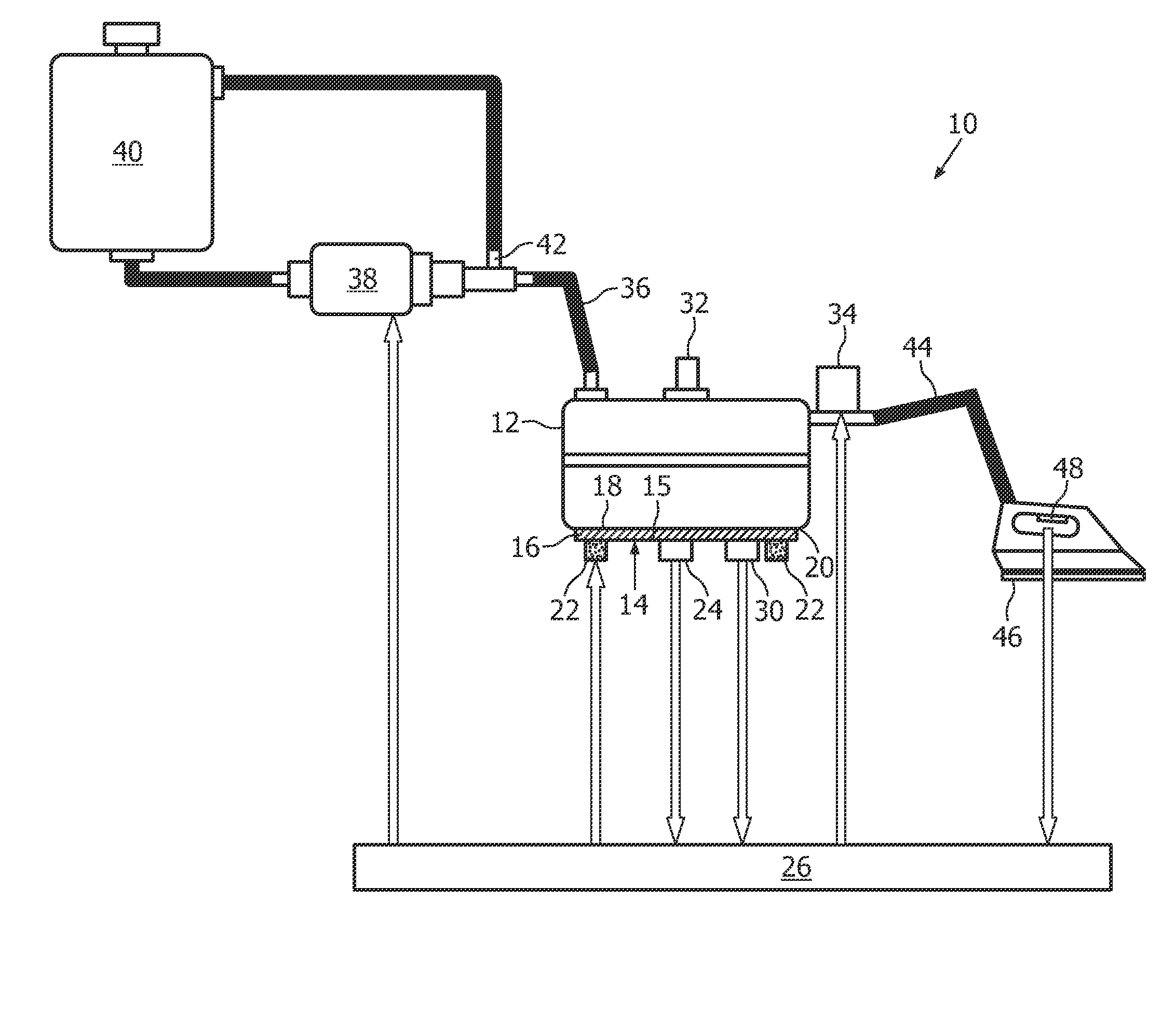
The invention is a steam generating apparatus that uses an intermetallic layer for a rigid mechanical attachment and good heat transfer between the heating device and the body of the apparatus. The apparatus includes a temperature sensor for measuring the pressure inside the body. The heating device is made of a first metal and the body is made of a second metal, which are connected by an intermetallic layer. The intermetallic layer ensures a uniform and high-quality heat transfer. The first metal is stainless steel for low corrosion and good heat transfer, while the second metal is aluminum or an aluminum alloy for good thermal conductivity and processing properties. The heating device has control means for controlling the temperature of the water, which ensures an accurate control of the steam pressure. The invention also includes a second time period and a corresponding set temperature that can be adjusted based on the expected steam output or water input. This improves the controlling of the steam pressure.

Problems solved by technology

Arranging the temperature sensor at the side walls requires a flat portion for a proper mounting of the sensor, which in turn complicates the forming of the shell.
Attaching the temperature sensor at the bottom of the boiler shell also is disadvantageously.
However, the heat transfer between the boiler shell and the heating plate is not optimal.
This causes a time delay in the temperature-time curve at the sensing location compared with the temperature-time curve of the water, since the heat transfer from the heating element into the water is considerably delayed.
This tends to cause either an overshooting of the steam pressure or the opposite.

Method used


Image

  • Apparatus and method for generating steam
  • Apparatus and method for generating steam
  • Apparatus and method for generating steam

Examples


first embodiment

[0033]FIG. 3 shows a method of controlling the pressure of steam according to the invention. In step S20, the nominal temperature Tnom of water to be heated is set to a first temperature T1. In step S21, a number of N temperature cycles as described in connection with FIG. 2 are performed. In step S22, the nominal temperature Tnom is set to a second temperature T2, the second temperature T2 being higher than the first temperature T1. In step S23, M temperature cycles are performed at the higher nominal temperature T2. Afterwards, in step S24, the nominal temperature Tnom is lowered to a third temperature T3, the third temperature T3 being lower than the second temperature T2. After performing K temperature cycles, the process continues with step S20 or, alternatively, with step S22. Thus, a higher temperature level T2 is provided during M temperature cycles allowing the generation of a higher pressure range.

second embodiment

[0034]FIG. 4 shows a method of controlling the pressure of steam according to the invention. In step S30, the nominal temperature Tnom of water to be heated is set to a first temperature T1. Afterwards, in step S31, a—preferably not predetermined—number of temperature cycles as defined above is performed. During these temperature cycles, the activation of a steam trigger, i.e. the initiation of a steam output, and the activation of the water pump are monitored (S32). If one of the mentioned events takes place, the process continues in step S33. Otherwise, the monitoring continues in step S32. In step S33, the heating element is turned on and the water is heated. During this heating, several events are monitored. If one of the events takes place, the heating element is turned off. First, in step S34, the current temperature of the water, Tcurr, is compared with a maximum temperature Tmax. If the current temperature Tcurr exceeds the maximum temperature Tmax, the heating element is tu...


PUM


Abstract

A steam generating apparatus includes a body for receiving water to be heated and has a first portion including a first metal, and a heating device having a second portion including a second metal. The heating device includes a heating plate connected with the body by forming an intermetallic layer between the first and second portions. A temperature sensor measures temperature indicative of pressure inside the body and thermally contacts the heating device outside the body. A method of controlling the pressure of steam in the steam generating apparatus includes setting the target water temperature for a first time period to a first set temperature; setting the target water temperature for a second time period to a second set temperature higher than the first set temperature; and setting the target water temperature for a third time period to a third set temperature lower than the second set temperature.

Description

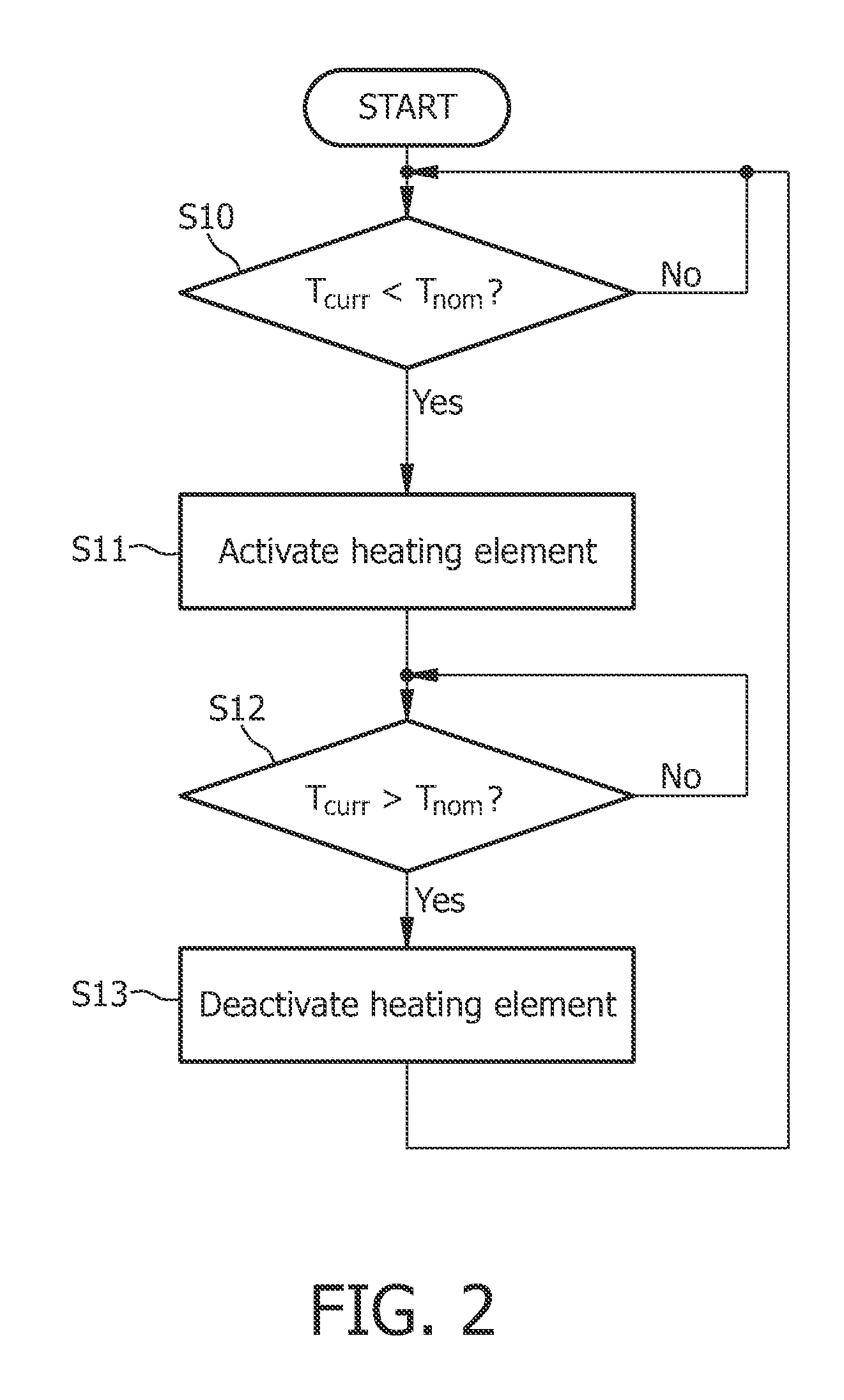
FIELD OF THE INVENTION[0001]The present invention generally relates to a steam generating apparatus and to a method of controlling the pressure of steam in a steam generating apparatus. In particular, the invention relates to a steam generating apparatus having improved heat transfer properties and to a method of controlling the pressure of steam in a steam generating device on the basis of these heat transfer properties.BACKGROUND OF THE INVENTION[0002]The heating of water, e.g. for generating steam, may be performed in water heating apparatuses or boilers. In these systems, the temperature of the water can be controlled within a certain temperature range by means of a heating device and a temperature sensor as follows: When the temperature signal of the temperature sensor indicates, that the temperature of the water falls below a certain level, the heating device is activated and the water is heated. If the temperature signal indicates, that the water temperature rises above a cer...

Claims


Application Information

Patent Timeline
Patent Type & Authority Patents(United States)
IPC IPC(8): F22B1/30
CPCF22B1/285F22B35/00F22B1/00F22B1/28
Inventor XIAO, TAIKANGRETHMEIER, ROEL ALEXANDERTHIRUMAZHISAI SANKARALINGAM, TAMILSELVANTAY, BARRY ENG KEONGTIEW, HOCK SOONBELLE, CHAITRA
Owner KONINK PHILIPS ELECTRONICS NV
Learn More