Motion robust depth estimation using convolution and wavelet transforms

a wavelet transform and convolutional wave technology, applied in the field of depth estimation, can solve the problem that the passive system is notoriously poor at making focal decisions in low contrast conditions

Active Publication Date: 2014-01-07
SONY CORP
View PDF12 Cites 10 Cited by
  • Summary
  • Abstract
  • Description
  • Claims
  • Application Information

AI Technical Summary

Benefits of technology

[0022]A method of camera depth estimation is described which is based on blur differences and multiple picture matching. This method computes a blur difference between images captured at different focus positions. The present invention utilizes a novel mechanism for determining the difference (blur) between images. Previous systems utilized some form of norm operator applied to the pixel-to-pixel difference between those images to compare the two images after convolution. In the inventive technique, a wavelet transform is applied to the images after convolution, and is followed by a calculation of variance of the wavelet coefficients. A difference of the two variances is then determined, such as preferably an absolute difference. As a consequence not needing to compare each pixel in a first image to a corresponding pixel position in a second image, apparatus and methods according to the invention provide a motion robust form of blur determination which is described herein within a system for estimating subject depth.
[0034]At least one embodiment of the invention utilizes a focus matching model based on imaging calibration targets obtained at different focal lengths. At least one embodiment of the invention is configured to utilize at least one size kernel when performing convolutions. For example, larger kernels may be used first to speed convergence, with progressively smaller kernels utilized to obtain the desired level of accuracy. At least one embodiment of the invention is configured for determining differences of wavelet variance, preferably an absolute difference of wavelet variances. At least one embodiment of the invention is configured for determining wavelet variance in at least one wavelet subband and at least one wavelet transform level. At least one embodiment of the invention is configured for determining wavelet variance in all wavelet subbands in at least one wavelet transform level. At least one embodiment of the invention is configured with the focus matching model utilizing a polynomial function, of any desired degree, to reduce mismatching noise. At least one embodiment of the invention is configured with coefficients of the polynomial function stored in memory.
[0035]At least one embodiment of the invention is configured for performing optional histogram matching of the object images to reduce noise from outliers between focal positions prior to inputting the blur differences into the focus matching model. Histogram matching need not be used in applications subject to significantly complex motions. At least one embodiment of the invention is configured for performing histogram matching in response to the steps comprising: (a) sequentially shifting pixels from a first histogram to a second histogram to equalize the pixels of closest luminance; and (b) approximating histogram matching utilizing a linear matching function; wherein noise effects are reduced which have been introduced into the focus matching model in response to undesired physical and environmental variations.
[0049]Another element of the invention is a histogram matching method in which pixels are sequentially shifted from one histogram to the other to equalize the pixels of closest luminance in the other histogram to reduce the effects of noise introduced into the model in response to undesired physical and environmental variations, and is approximated by a linear matching function.

Problems solved by technology

Passive systems are notoriously poor at making focal decisions in low contrast conditions, notably on large single-colored surfaces (solid surface, sky, and so forth) or in low-light conditions.

Method used


Image

  • Motion robust depth estimation using convolution and wavelet transforms
  • Motion robust depth estimation using convolution and wavelet transforms
  • Motion robust depth estimation using convolution and wavelet transforms

Examples


embodiment 10

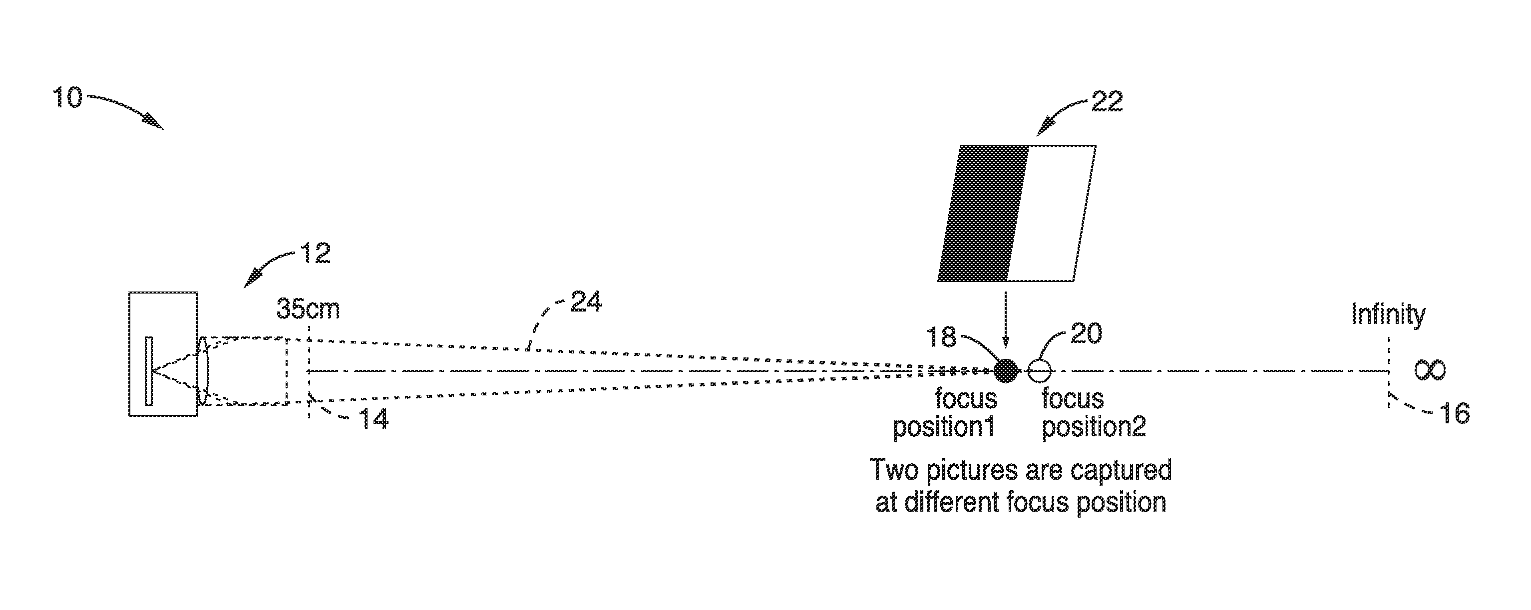
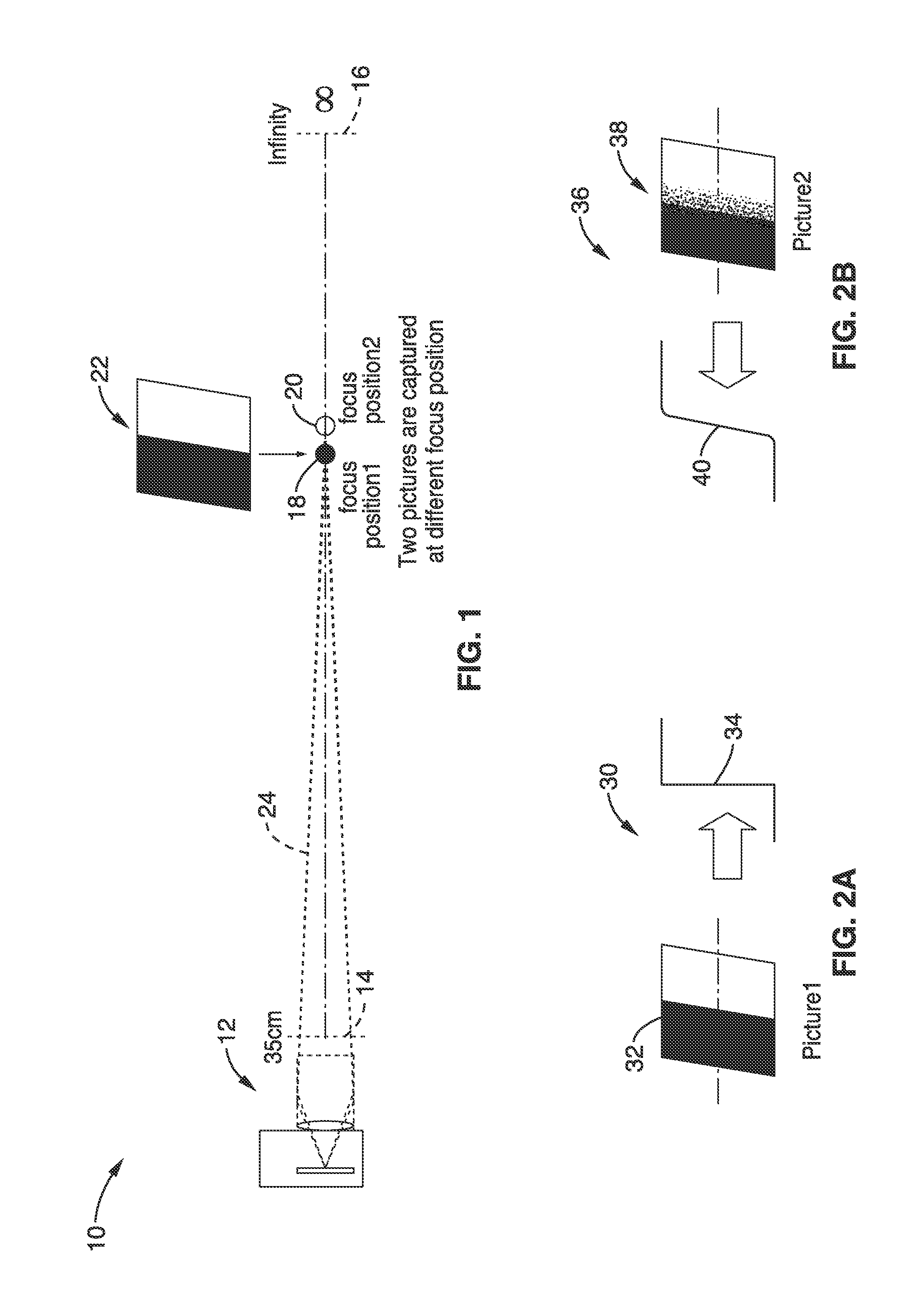
[0074]FIG. 1 illustrates an embodiment 10 in which multiple images are captured of a calibration target (or calibration subject), at different focal positions (subject-distances) when collecting a data set for a given imaging apparatus (e.g., specific embodiment, make or model of camera, or a family of cameras using the same / similar optical imaging elements). Collecting the data set comprises a characterization process for the camera-lens system at a given magnification setting (lens at a fixed focal length, zoom setting). An imaging device (camera) 12 is shown which can focus from a minimum focal length 14 on out to infinity 16. Minimum focal distance 14 (e.g., in this case 35 cm) is shown as well as focus at infinity 16. According to the invention, the focus converges to first focal position 18 and then to a second focal position 20, upon a calibration target 22, such as step-edge image, slate, graticule, or similar target having known optical characteristics, along focal path 24....

embodiment 1

[0152]2. The apparatus of embodiment 1, wherein said focus matching model is based on imaging calibration targets obtained at different focal lengths.

[0153]3. The apparatus of embodiment 1, wherein programming executable on said computer processor is configured for performing said convolutions by at least one size of convolution kernel.

[0154]4. The apparatus of embodiment 1, wherein programming executable on said computer processor is configured for determining said differences of wavelet variance in response to a determination of absolute wavelet differences.

[0155]5. The apparatus of embodiment 1, wherein programming executable on said computer processor is configured for determining said wavelet variance in at least one wavelet subband and at least one wavelet transform level.

[0156]6. The apparatus of embodiment 1, wherein programming executable on said computer processor is configured for determining said wavelet variance in all wavelet subbands in at least one wavelet transform ...

embodiment 7

[0158]8. The apparatus of embodiment 7, wherein coefficients of the polynomial function are stored in said memory.

[0159]9. The apparatus of embodiment 1, wherein programming executable on said computer processor is further configured for performing histogram matching of the object images to reduce noise from outliers between focal positions prior to inputting the blur differences into the focus matching model.


PUM


Abstract

Apparatus and method for electronically estimating focusing distance between a camera (still and / or video camera) and a subject. Images at different focal positions of a calibration target are collected to arrive at a focus matching model for a given imaging apparatus. In operation, at least two images are captured and convolutions performed which approximate the modeling of blur change as a point spread function. Wavelet transforms are applied to the images after each convolution and images are compared based on the wavelet variance differences to provide a motion robust blur difference determination. Applying the blur differences to the focus matching model provides an estimate of focusing distance, which can be utilized such as for controlling camera focus.

Description

CROSS-REFERENCE TO RELATED APPLICATIONS[0001]Not ApplicableSTATEMENT REGARDING FEDERALLY SPONSORED RESEARCH OR DEVELOPMENT[0002]Not ApplicableINCORPORATION-BY-REFERENCE OF MATERIAL SUBMITTED ON A COMPACT DISC[0003]Not ApplicableNOTICE OF MATERIAL SUBJECT TO COPYRIGHT PROTECTION[0004]A portion of the material in this patent document is subject to copyright protection under the copyright laws of the United States and of other countries. The owner of the copyright rights has no objection to the facsimile reproduction by anyone of the patent document or the patent disclosure, as it appears in the United States Patent and Trademark Office publicly available file or records, but otherwise reserves all copyright rights whatsoever. The copyright owner does not hereby waive any of its rights to have this patent document maintained in secrecy, including without limitation its rights pursuant to 37 C.F.R. §114.BACKGROUND OF THE INVENTION[0005]1. Field of the Invention[0006]This invention perta...

Claims


Application Information

Patent Timeline
Patent Type & Authority Patents(United States)
IPC IPC(8): H04N5/228H04N5/225
CPCH04N5/23212G06T2207/20064G06T7/0069G06T7/571H04N23/676
Inventor LI, PINGSHAN
Owner SONY CORP
Why Eureka
Try Eureka