Dual band electrically small tunable antenna

a tunable antenna, electrically small technology, applied in the direction of electrically short antennas, antenna details, antennas, etc., can solve the problems of reducing antennas, reducing antennas, reducing antennas, etc., and achieves a moderate antenna gain

Inactive Publication Date: 2014-01-14
CHARLES STARK DRAPER LABORATORY
View PDF3 Cites 218 Cited by
  • Summary
  • Abstract
  • Description
  • Claims
  • Application Information

AI Technical Summary

Problems solved by technology

The RF antenna becomes the limiting factor in the size of many devices.
As the size of the antenna is reduced below a quarter wavelength, either the gain or bandwidth suffers.
As a result, to maintain a moderate gain level, a system may have to contend with very narrow bandwidths for the antenna.
Narrow bandwidth leaves the antenna susceptible to being pulled off frequency when placed near external objects.

Method used


Image

  • Dual band electrically small tunable antenna
  • Dual band electrically small tunable antenna
  • Dual band electrically small tunable antenna

Examples


Embodiment Construction

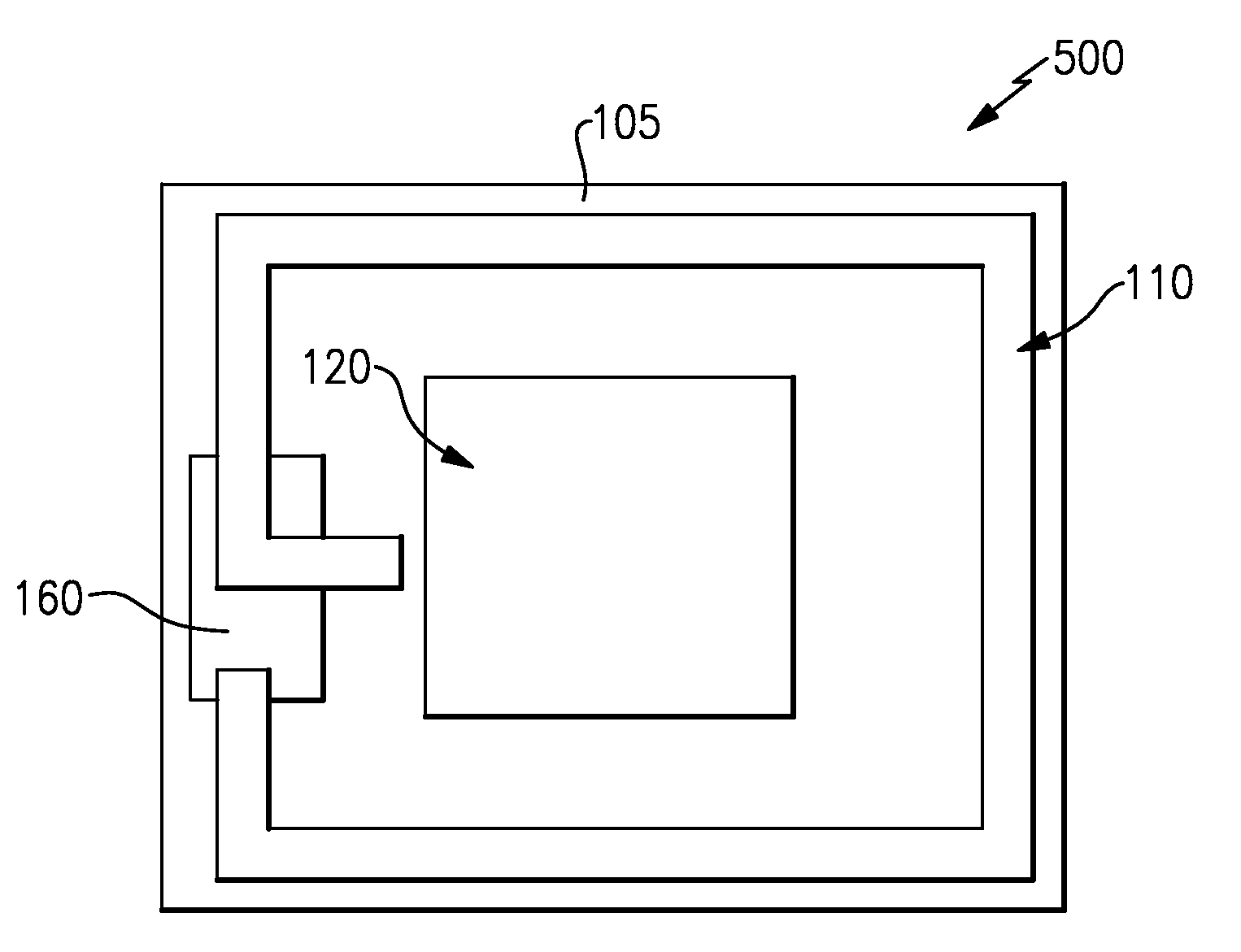
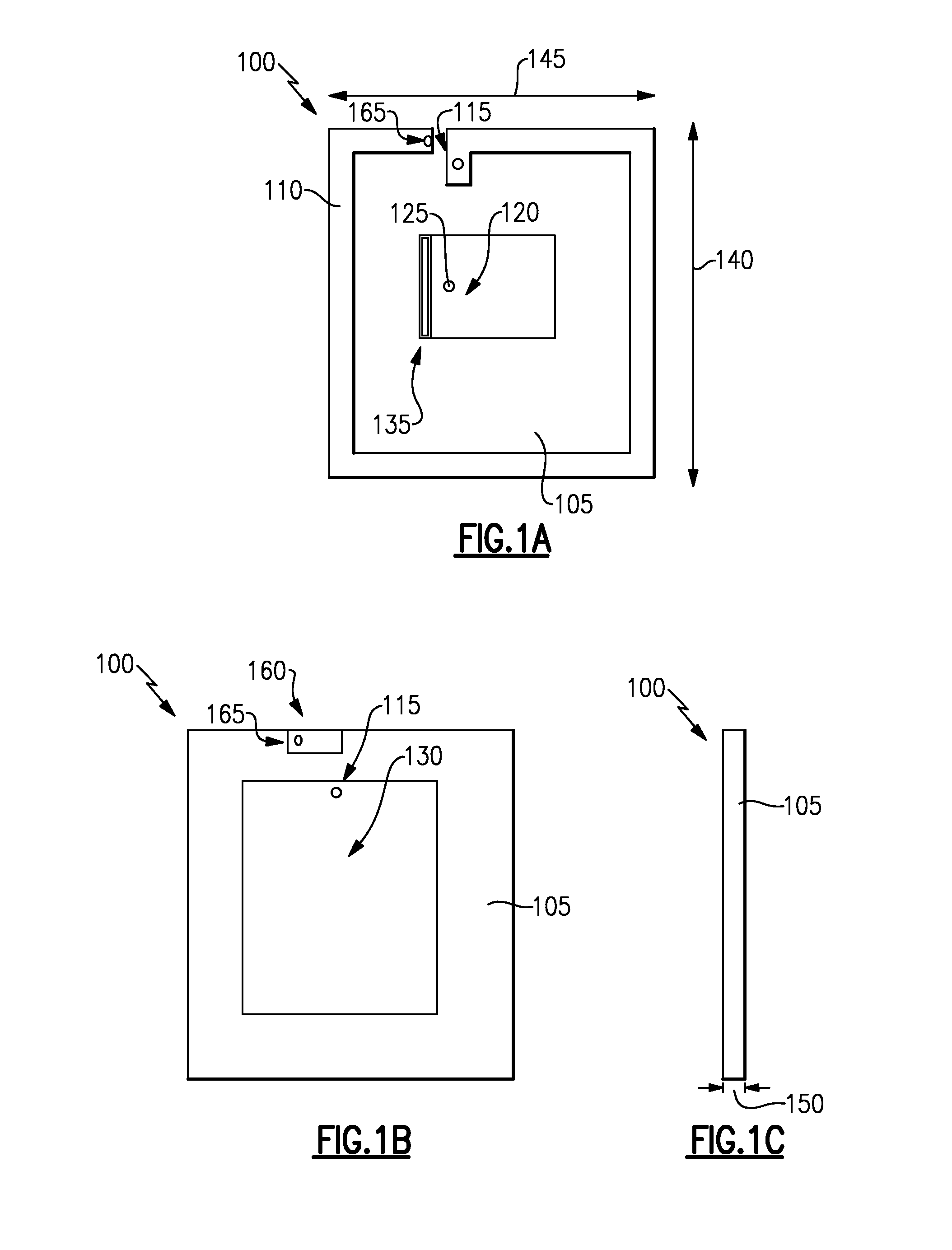
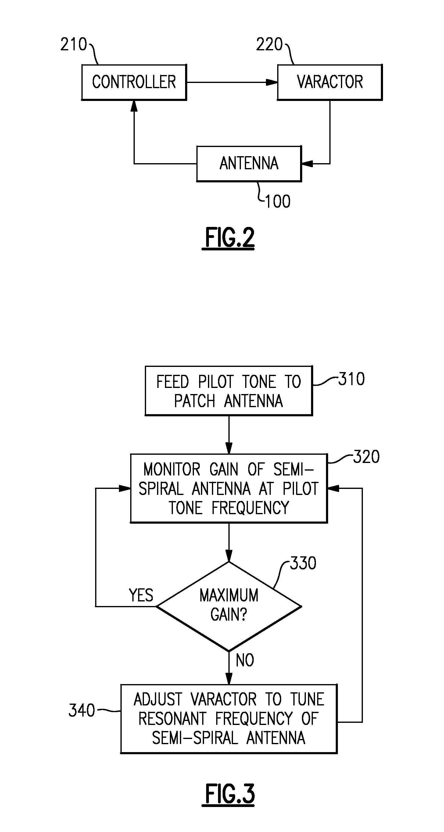
[0020]Aspects and embodiments are directed to a dual-band, tunable electrically small antenna capable of providing moderate antenna gain within a compact structure. An electrically small antenna is one whose physical dimensions (e.g., length and / or width) are small relative to the operating wavelength of the antenna, for example, less than about one quarter wavelength. Generally, electrically small antennas have high Qs (narrow bandwidths). As a result, the antenna may be easily pulled off the desired frequency when placed near external objects. To mitigate this issue, embodiments of the dual-band antenna have a self-tuning capability in which a feedback loop is used to maintain a desired resonant frequency of the antenna, as discussed in more detail below.

[0021]It is to be appreciated that embodiments of the methods and apparatuses discussed herein are not limited in application to the details of construction and the arrangement of components set forth in the following description ...


PUM


Abstract

An electrically small dual-band planar tunable UHF / L-Band antenna. In one example, the dual-band antenna includes a combination of a semi-spiral antenna for the UHF frequencies and a microstrip patch antenna for the L-band frequencies.

Description

BACKGROUND[0001]Numerous communications and navigation systems are multi-band, covering two or more different frequency bands for different applications or compatibility with different systems around the globe. For example, a system may be configured to cover the UHF (ultra high frequency; approximately 300-3000 MHz) band, GPS (global positioning system) frequencies, and satellite communication frequency bands, such as those used by the Iridium™, SATCOM™ and GPS systems. A majority of systems would use multiple antennas to cover the UHF / GPS / Iridium™ bands.[0002]Modern day technology and fabrication methods have allowed electronic components such as radio frequency (RF) receivers and processing electronics to be packaged in extremely small housings. The RF antenna becomes the limiting factor in the size of many devices. As the size of the antenna is reduced below a quarter wavelength, either the gain or bandwidth suffers. As a result, to maintain a moderate gain level, a system may h...

Claims


Application Information

Patent Timeline
Patent Type & Authority Patents(United States)
IPC IPC(8): H01Q1/00
CPCH01Q1/38H01Q7/005H01Q5/0072H01Q9/0421H01Q9/0442H01Q5/40
Inventor GRANDFIELD, JOHN E.ABBAN, MICHAEL P.GAYNOR, BRAD D.
Owner CHARLES STARK DRAPER LABORATORY
Why Eureka
Try Eureka