Apparatus and method for a multiple aperture coherent ladar

a coherent ladar and multiple aperture technology, applied in distance measurement, instruments, surveying and navigation, etc., can solve the problems of synthetic aperture ladars that are extremely sensitive to uncompensated motion and the implementation of ifsar techniques at optical wavelengths, so as to reduce the complexity of multi-aperture coherent ladar hardware, reduce the complexity of system complexity, and simple robust modulators

Inactive Publication Date: 2014-01-14
UNITED STATES OF AMERICA AS REPRENSENTED BY THE SEC OF THE AIR FORCE THE
View PDF12 Cites 25 Cited by
  • Summary
  • Abstract
  • Description
  • Claims
  • Application Information

AI Technical Summary

Benefits of technology

[0010]The present invention can also provide synthetic aperture imaging, which is substantially immune to undesired radial platform motions. When the ladar apertures are oriented in the along-track dimension, the invention enables the multi-aperture phase retrieval required for differential synthetic aperture ladar (DSAL). Multiple apertures within the along-track dimension reduce conventional synthetic aperture imaging times, or baseline motion, when the multiple apertures are oriented in the along-track dimension. System complexity can be reduced and can be implemented with relatively simple robust modulators. Implementation can be accomplished with multiple transmitters or using an optical delay for code generation.
[0011]The use of an optical delay to transmit, detect, and process PPN waveforms in CDMA ladar can reduce the complexity of multi-aperture coherent ladar hardware. A single laser and modulator can be used to produce orthogonal signals transmitted from each aperture. Phase measurement accuracy can be improved since exact waveform copies are transmitted with delay from each aperture. Also improved is the accuracy of phase measurement since all signals received from all transmit apertures are processed on a single receiver. The use of CDMA reduces hardware complexity since a single receiver channel is used to detect the signal from multiple apertures. The use of CDMA reduces the signal processing load since a single matched filter operation produces the output for all transmit paths received by an aperture.
[0012]The use of continuous wave PPN waveforms in coherent ladar provides a high duty cycle waveform and increases performance by pseudo noise waveform. Because of its binary phase, a PPN waveform is a high time bandwidth waveform enabling multiple imaging modes by simply changing post processing algorithms. The waveform allows adaptable Doppler sensitivity by selectively processing different sub-code lengths. The PPN waveform also allows adaptable energy

Problems solved by technology

Implementing IFSAR techniques at optical wavelengths is extremely challenging and can be impacted by phase variations from a variety of sources, including variations between the two aper

Method used


Image

  • Apparatus and method for a multiple aperture coherent ladar
  • Apparatus and method for a multiple aperture coherent ladar
  • Apparatus and method for a multiple aperture coherent ladar

Examples


Embodiment Construction

[0019]Each of the above described systems of coherent ladar require detailed and accurate measurements of the phase of the individual return signals as well as the phase between the signals being received by the apertures. The present invention includes a method and apparatus to measure the required return phase of signals and the phase between the signals returned by respective apertures using PPN waveforms in a CDMA architecture. The technique uses a multiple sub-code PPN waveform, as shown in Table 1, to phase two or more physical apertures and allows multi-input, multi-output (MIMO) operation.

[0020]

TABLE 1Composite binary phase code consisting of CNcode sequentialorthogonal sub-codes.

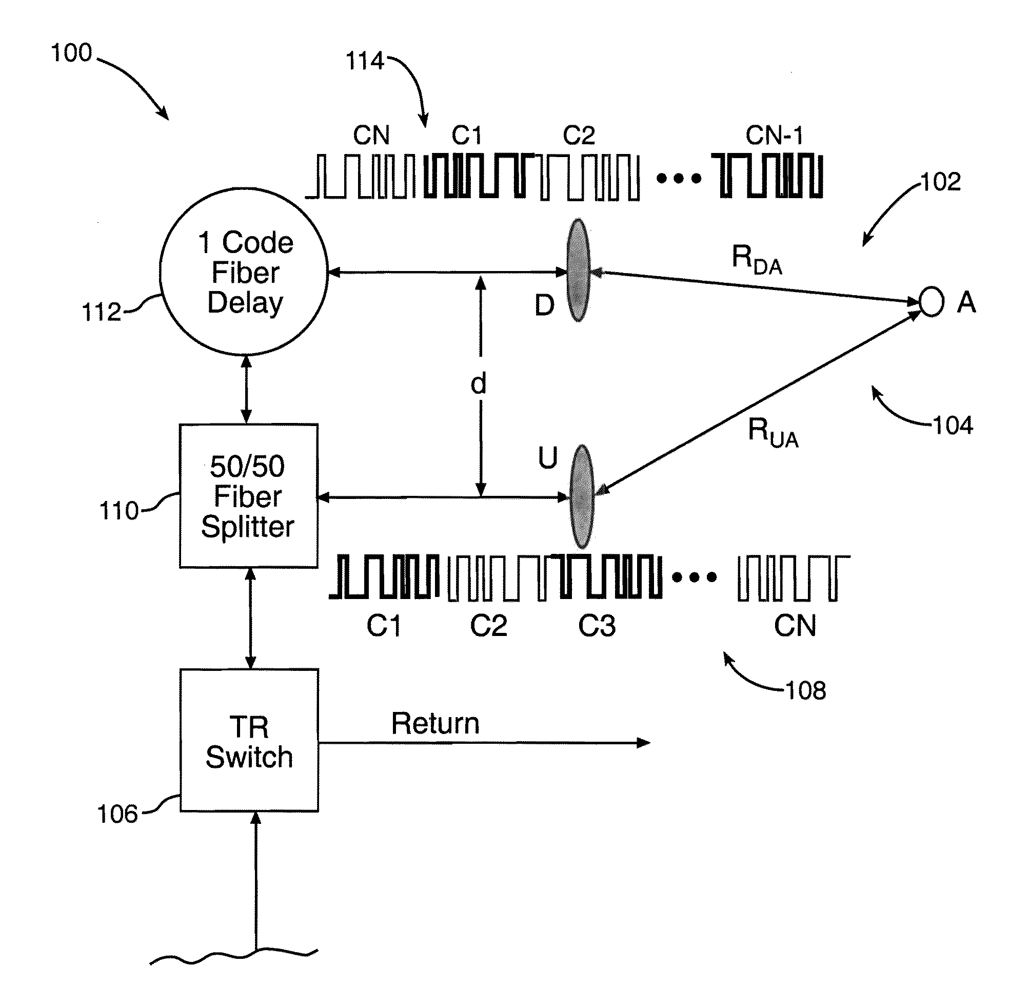
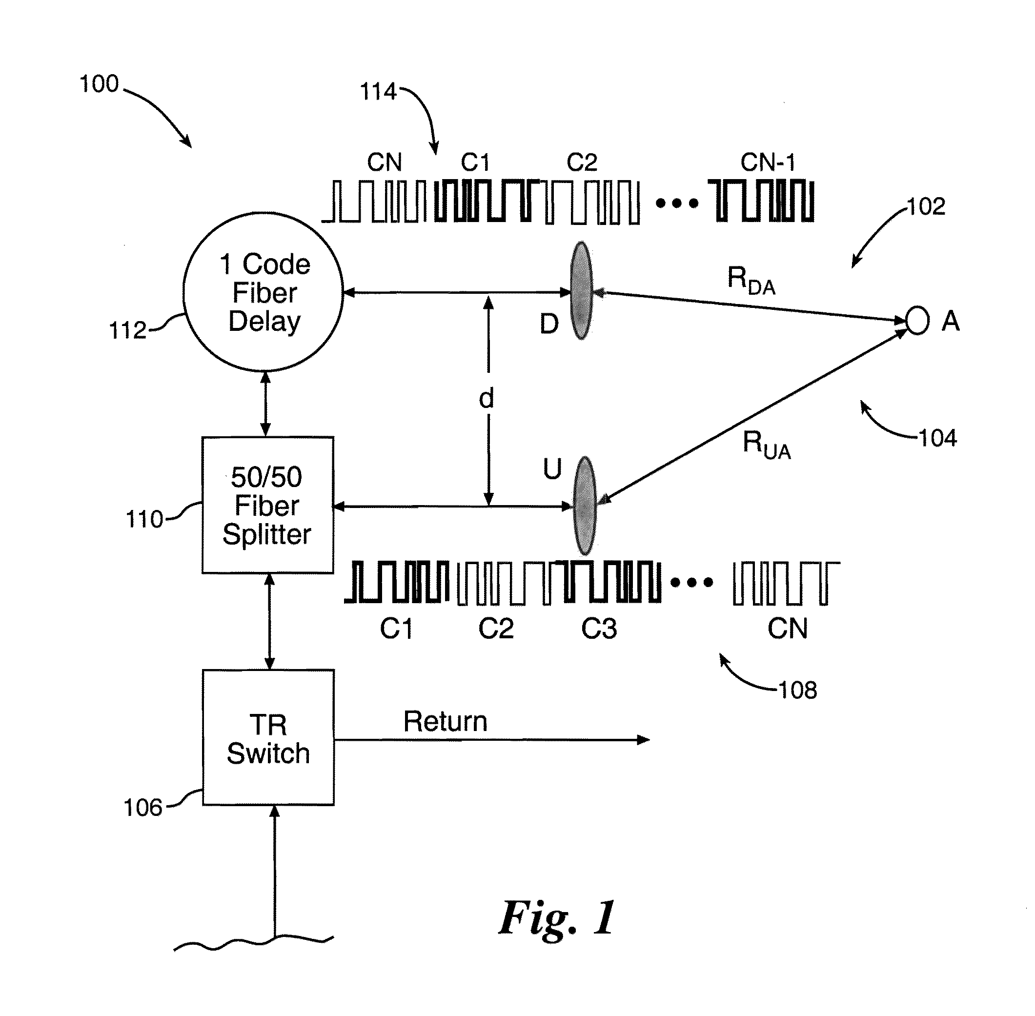
[0021]FIG. 1 illustrates one conceptual example of a CDMA implementation in a multiple aperture ladar system 100. By introducing a one sub-code delay between the apertures, orthogonal sub-codes may be transmitted and received from each of the apertures simultaneously, and a multiple-input, multiple-...


PUM


Abstract

A multi-function, range-Doppler, synthetic aperture and micro-Doppler, coherent laser radar system having improved spatial resolution and immunity to undesired platform motion utilizing two or more simultaneous, spatially offset transceiver apertures.

Description

RIGHTS OF THE GOVERNMENT[0001]The invention described herein may be manufactured and used by or for the Government of the United States for all governmental purposes without the payment of any royalty.BACKGROUND OF THE INVENTION[0002]Remote sensing coherent ladar (laser radar) imaging systems can provide images at ranges far beyond the useful range of a traditional diffraction limited imaging systems. Coherent ladar relies on phase sensitive measurements to resolve an object and provide information about its motion. To overcome the diffraction limitations of a finite aperture system, synthetic aperture ladar (SAL) systems use multiple spatial samples from a single small aperture in motion to synthesize a larger effective aperture. This results in higher spatial resolution, but only in the along-track dimension (i.e., in the direction of flight) in which the samples were collected. Conventional SAL imaging has been demonstrated both in the laboratory as well as in flight, but is sens...

Claims


Application Information

Patent Timeline
IPC IPC(8): G01C3/08
CPCG01S17/87G01S7/4818G01S17/895G01C3/08G01S17/90
Inventor DIERKING, MATTHEW P.DUNCAN, BRADLEY D.
Owner UNITED STATES OF AMERICA AS REPRENSENTED BY THE SEC OF THE AIR FORCE THE
Why Eureka
Try Eureka