Composite repair for pipes and monitoring assembly

a technology for monitoring assembly and pipes, applied in the direction of hose connection, fluid tightness measurement, instruments, etc., can solve the problems of time-consuming and costly repair types, and achieve the effects of preventing excessive pressure buildup, slow dispersion of leaked substances, and high density of leaked substances

Inactive Publication Date: 2014-01-21
ODYSSIAN TECH
View PDF6 Cites 25 Cited by
  • Summary
  • Abstract
  • Description
  • Claims
  • Application Information

AI Technical Summary

Benefits of technology

[0029]The sensor housing can be mounted underground and access achieved through a conduit extending above ground in form of a pipe or marker, wires extending from the housing to provide connection to a hand-held device plugged in to read the sensor or connected to a wired or wireless communication and control network. The housing may also provide a secondary containment structure that, in addition to sensing leaks and health of the containment device, provides secondary leak protection by surrounding the structure.
[0030]The sensor housing can be a robust structure intended for long term use and containment of pressurized fluid or a less robust structure intended for temporary use. The housing may slow dispersion of leaked substances to achieve a high density of the leak substance as may be required for leak detection sensing. The housing may include an outer shell, which is porous, allowing high pressure fluid to pass to prevent excessive buildup of pressure in the housing and rupture of containment, yet slows down dispersion to cause a higher concentration of leak substance for improved sensing. The monitoring assembly may include a soft or compliant secondary structure including a tape wrap or spray covering.

Problems solved by technology

Corrosion, cracking, ground shifting, excavation, or other accidents or environmental damage may cause the need for a localized repair in a pipe, where the majority of the pipe is still suitable for use.
This type of repair can be costly and time-consuming, as well as requiring the flow to be cut off and the pipe emptied or evacuated in order to complete the repair.

Method used


Image

  • Composite repair for pipes and monitoring assembly
  • Composite repair for pipes and monitoring assembly
  • Composite repair for pipes and monitoring assembly

Examples


Embodiment Construction

[0064]For the purposes of promoting an understanding of the principles of the invention, reference will now be made to the embodiments illustrated in the drawings, which are described below. It will nevertheless be understood that no limitation of the scope of the invention is thereby intended. The invention includes any alterations and further modifications in the illustrated devices and described methods and further applications of the principles of the invention, which would normally occur to one skilled in the art to which the invention relates.

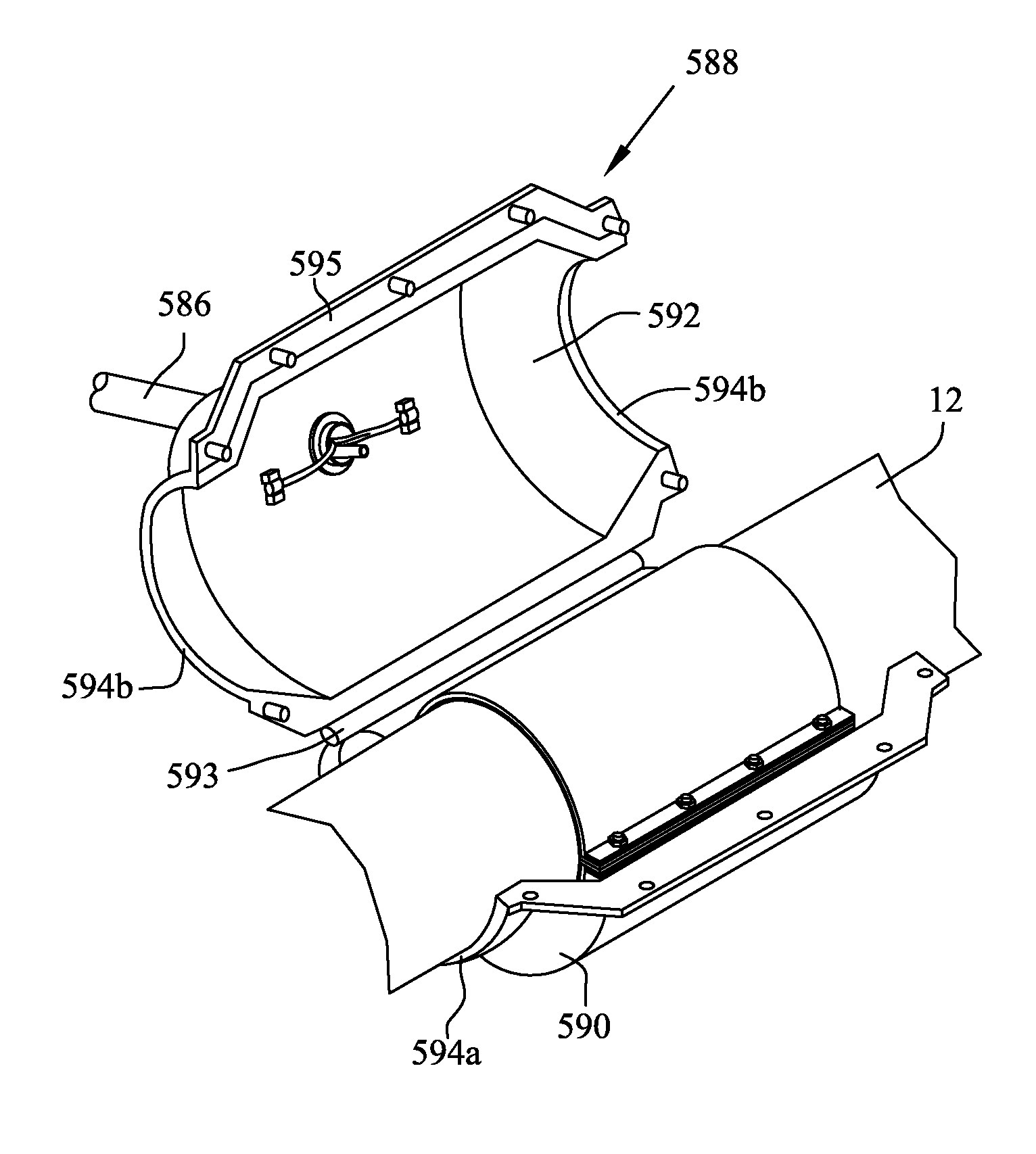
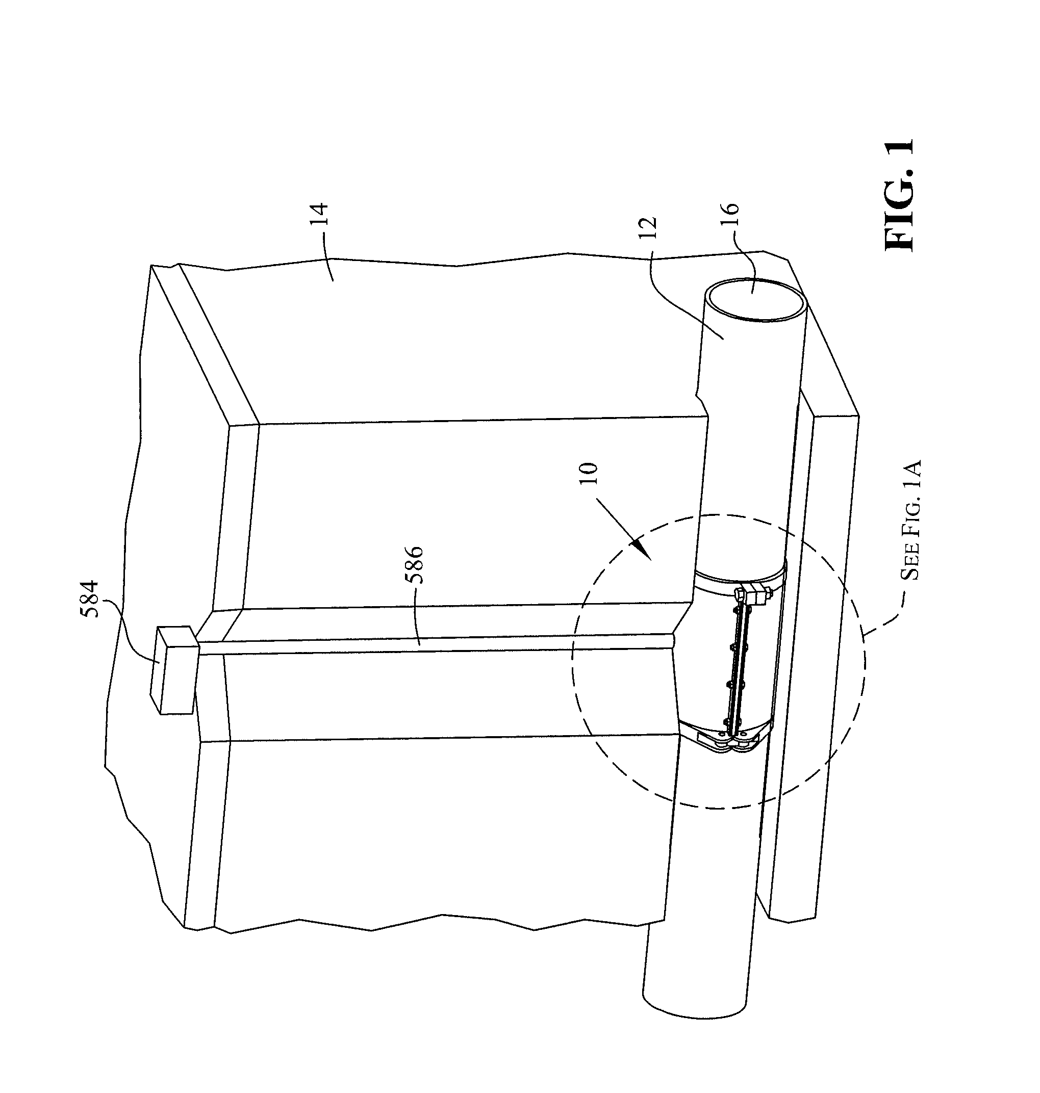
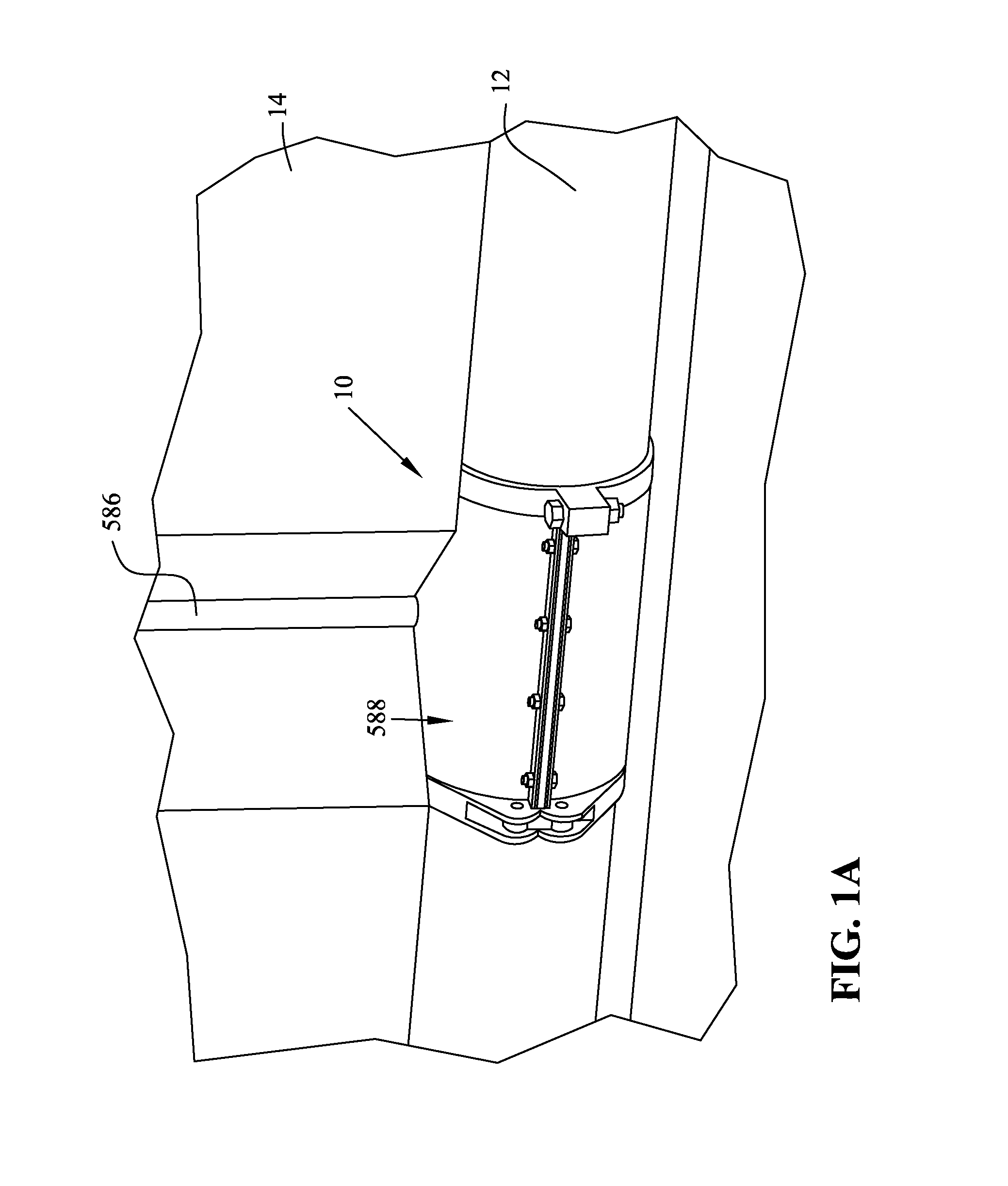
[0065]Now referring to FIGS. 1 and 1A, a composite repair assembly, generally indicated as 10, is shown for a field installation repair. Composite repair assembly 10 is installed on a pipe or pipeline 12, which is mounted in or under the ground 14. Pipe 12 includes an internal passageway 16 through which a material (not shown) to be transported through pipe 12 is contained. Composite repair assembly 10 may be used to prepare a localized d...


PUM

PropertyMeasurementUnit
internal diameteraaaaaaaaaa
diameteraaaaaaaaaa
densityaaaaaaaaaa

Abstract

A method and assembly for monitoring at least one condition outside of a containment device containing a gaseous or fluid substance and an inlet and outlet attached to the containment device. The method includes the steps of providing a monitoring system having a housing surrounding the containment device extending an inlet and outlet through openings in the housing; sealing the housing and sealing around the inlet and outlet so that a cavity internal to the housing is sealed from the exterior environment; providing at least one sensor located in the cavity between the containment device and the housing; connecting the sensor to a unit for monitoring the sensor; sensing at least one parameter indicative of a leak or potential leak of the containment device or attachment of the containment device to the inlet or outlet; and providing alerts of the leak or potential leak.

Description

[0001]This is a Continuation-In-Part application claiming priority from Non-provisional U.S. patent application Ser. No. 12 / 657,316 filed Jan. 19, 2010, the entirety of which is incorporated by reference herein.BACKGROUND OF THE INVENTION[0002]The present invention pertains to a repair assembly and method for repairing pipes in the field, and in particular, to a repair assembly and method that includes a composite repair material that is heated in the field.[0003]Pipes that are installed in the field or other industrial applications may be used for a multitude of purposes, such as for carrying water, sewer, gas, oil, chemicals, or other well known uses. During the course of a pipeline's use, it may become necessary to make repairs. Corrosion, cracking, ground shifting, excavation, or other accidents or environmental damage may cause the need for a localized repair in a pipe, where the majority of the pipe is still suitable for use.[0004]One conventional way of repairing a pipe is to...

Claims


Application Information

Patent Timeline
Patent Type & Authority Patents(United States)
IPC IPC(8): F16L55/00
CPCG01M5/0025B29C66/52272B29C73/10B29C63/22F16L55/168F16L55/172B29C66/81261B29C66/81457G01M3/243B29C65/562G01M5/0041B29C66/532B29C73/34B29C63/0047B29C66/73921G01M3/223G01M3/2815B29C66/1312B29C66/8284B29C73/30G01M3/002B29C63/0069B29C66/547B29C73/04B29C65/18B29C2035/043B29C66/71B29C66/7392B29C66/81241B29C66/81821B29K2023/065B29K2077/00B29K2069/00B29K2033/12B29K2025/06
Inventor BENNETT, BARTON, E.
Owner ODYSSIAN TECH
Why Eureka
Try Eureka