Apparatus for condensing light from multiple sources using Bragg gratings

a technology of condensing light and bragg grating, which is applied in the direction of lighting and heating apparatus, light source combinations, instruments, etc., can solve the problems of incoherent sources such as uhp lamps, short lamp lifetime, and high heat dissipation and power consumption

Active Publication Date: 2014-01-21
DIGILENS
View PDF12 Cites 79 Cited by
  • Summary
  • Abstract
  • Description
  • Claims
  • Application Information

AI Technical Summary

Benefits of technology

[0014]It is an object of the present invention to provide compact, efficient LED illuminator based on Bragg gratings.
[0015]It is a further object of the present invention to provide a compact and efficient illuminator capable of combining two light sources having similar peak wavelengths using a single grating.

Problems solved by technology

Illumination systems based on incoherent sources such as UHP lamps, for example, suffer from the problems of bulk, warm up time lag, high heat dissipation and power consumption, short lamp lifetime, noise (resulting from the color wheel) and poor color saturation.
However, illuminators based on LEDs suffer from several problems.
Although LEDs provide high lumen output they have large emittance angles, making the task of collecting and relaying light through the narrower acceptance cones of a microdisplay a very challenging optical design problem.
LEDs require fairly large collimators, making it difficult to achieve compact form factors.
LED triplet configurations using a shared collimation element suffer from thermal problems if the die are configured too closely.
In the case of X-cube architectures such as the one shown in FIG. 2, the resulting image is barely bright enough, with the X-cube itself losing around one third of the light from the LEDs.
X-cubes also present alignment, bulk and cost problems.
A volume phase grating is then recorded by illuminating the liquid material with two mutually coherent laser beams, which interfere to form the desired grating structure.
Although DOEs may be designed for any wavelength, providing a separate DOE for each source may be expensive and may lead to unacceptable attenuation and scatter when the elements are stacked.
However such devices suffer from reduced diffraction efficiency and throughput limitations imposed by the etendue of a grating.
However, if we consider the wavelength ranges of typical sources the resulting incidence angle range will not be sufficiently large to separate the LED die.
This would make it at best extremely difficult to integrate the LED die and condenser optics into a compact package.

Method used


Image

  • Apparatus for condensing light from multiple sources using Bragg gratings
  • Apparatus for condensing light from multiple sources using Bragg gratings
  • Apparatus for condensing light from multiple sources using Bragg gratings

Examples


Embodiment Construction

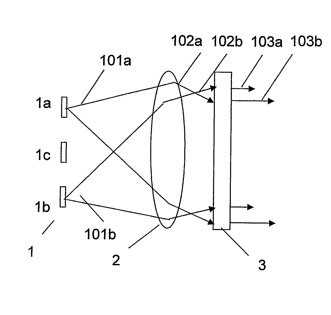
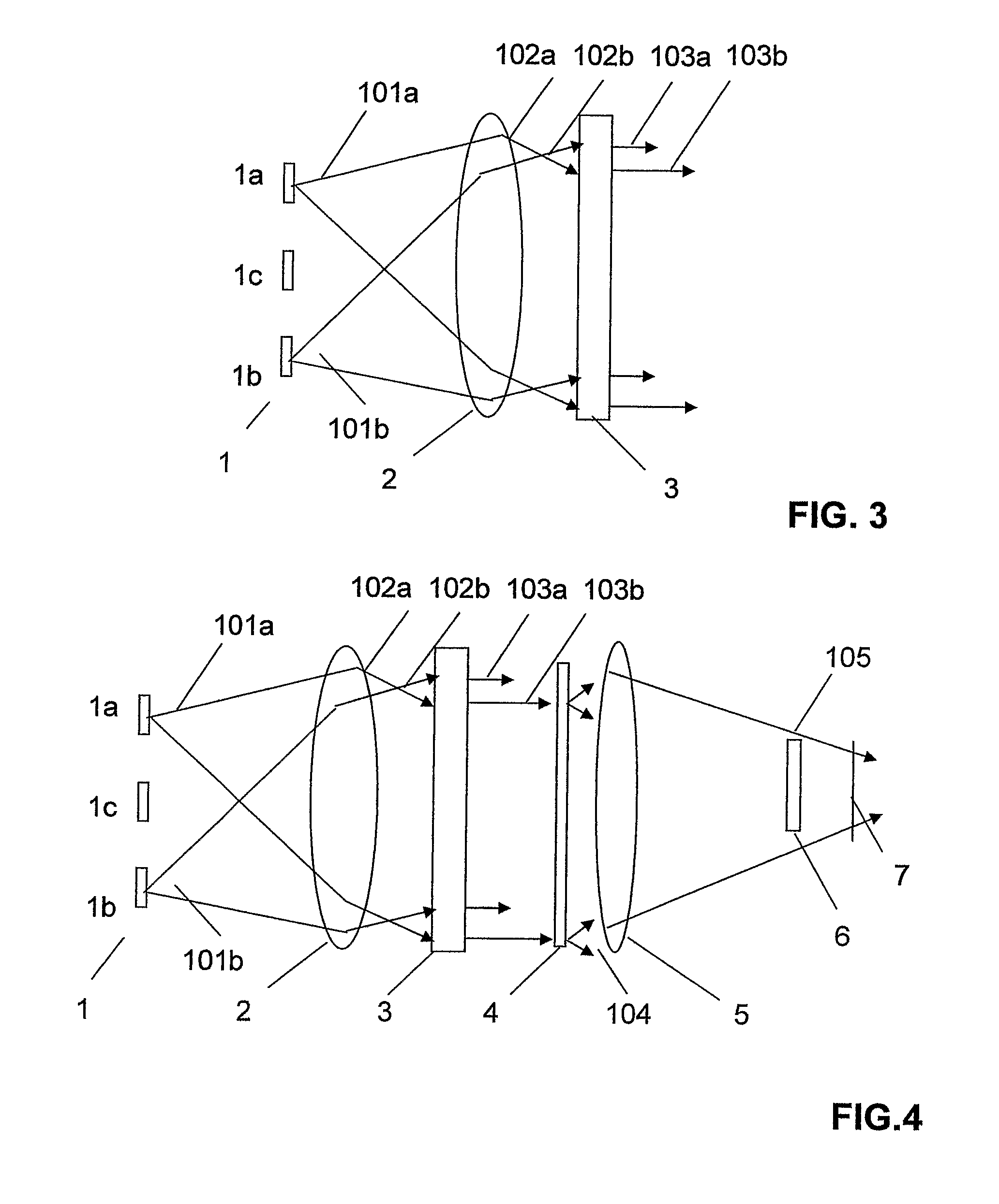
[0094]FIG. 3 shows a schematic side elevation view of a first embodiment of the invention. The illuminator comprises the LED module 1, condenser lens 2, and an ESBG device configured as a stack of separately switchable ESBG layers. Said optical elements are aligned along an optical axis normal to the surface of each element Each ESBG layer is recorded in HPDLC sandwiched between transparent substrates to which transparent conductive coatings have been applied. Each ESBG has a diffracting state and a non-diffracting state. Each ESBG diffracts light in a direction substantially parallel to the optical axis when in said active state. However, each ESBG is substantially transparent to said light when in said inactive state. Each ESBG is operative to diffract at least one wavelength of red, green or blue light. As shown in FIG. 3 the LED module comprises emitters 1a, 1b, 1c which would normally comprised red green and blue LEDs. Although only one LED of each colour is shown in FIG. 3 mor...


PUM


Abstract

A color sequential illumination device including in series: first and second light sources; a condenser lens; and a grating device. The grating device includes at least one Bragg grating. The condenser lens directs light from the first and second sources into the grating device at first and second incidence angles respectively. The grating device diffracts light from the first and second sources into a common direction. Desirably, the Bragg gratings are Electrically Switchable Bragg Gratings. In one embodiment the light sources are Light Emitting Diodes. Alternatively lasers may be used.

Description

CROSS-REFERENCE TO RELATED APPLICATION[0001]This application claims the benefit of U.S. provisional application Ser. No. 60 / 739,690 filed Nov. 25, 2005.[0002]This application, claims priority to United Kingdom patent application No. GB0516063.5 by one of the inventors, filed 11 Nov. 2005 and U.S. Provisional Patent Application No. 60 / 739,690 filed 25 Nov. 2005.BACKGROUND OF THE INVENTION[0003]This invention relates to an apparatus for illuminating a display, and more particularly to an illuminator device based on Bragg gratings.[0004]Recent developments in microdisplays and Light Emitting Diode (LED) technology are driving the development of a range of consumer applications such as compact projectors and thin form factor rear projection televisions. Current microdisplays employ a variety of technologies including liquid crystals, micro-mechanical mirrors (MEMs), micro-mechanical diffraction gratings and others. Liquid Crystal Displays (LCDs) are the most well known examples. The mos...

Claims


Application Information

Patent Timeline
Patent Type & Authority Patents(United States)
IPC IPC(8): G02B5/32
CPCG02B27/102G02B5/32G02B27/1086G02F2001/133613H04N9/3164G02F2203/62G02F2001/133607H04N9/3197F21K9/56G02B27/42H04N9/3152F21V5/04F21K9/64G02F1/133607G02F1/133613F21Y2113/13F21Y2115/10G02F1/133606
Inventor POPOVICH, MILAN MOMCILOWALDERN, JONATHAN DAVID
Owner DIGILENS
Why Eureka
Try Eureka