Process for manufacturing a bearing ring member as a constituent of a rolling bearing unit for wheel support

a technology of rolling bearing unit and bearing ring member, which is applied in the direction of mechanical equipment, transportation and packaging, and other domestic objects, can solve the problems of reduced processibility, increased processing cost of hub body, and difficulty in maintaining the shape and dimension precision of processed goods, so as to improve the precision of dimensions and reduce the cross-sectional area. , the effect of high precision

Active Publication Date: 2014-01-28
NSK LTD
View PDF16 Cites 0 Cited by
  • Summary
  • Abstract
  • Description
  • Claims
  • Application Information

AI Technical Summary

Benefits of technology

[0023]With the process for manufacturing a bearing ring member of a rolling bearing unit for wheel support of the present invention that is constructed as described above, it is possible to process, for example, a small-diameter section such as a small-diameter step section on the inside end section of a hub flat comprises an outward facing flange and positioning cylinder stably and with high precision.
[0024]That is, this small-diameter section is processed by cold forging, so it is possible to improve the precision of dimensions by keeping errors in dimensions due to differences in thermal expansion of the molds and object being processed (metal material) to a minimum. In addition, since the object being processed, which is a metallic material, is pressed into a receiving punch by a pressing punch with the outer peripheral surface of the metallic material being held by a floating die, the metallic material does not deform outward in the radial direction as shown in (C) of FIG. 20 described above. Therefore, the aforementioned small-diameter section can be processed stably even though there may be a large difference between the outer diameter of the metallic material and the outer diameter of the small-diameter section (there is a large rate of decrease of the cross-sectional area) or when the slope of the step section that connects between the small-diameter section and the remaining portion is large (the angle of the step section with respect to the center axis is a right angle or nearly a right angle).
[0025]Moreover, with the process for manufacturing a bearing ring member of a rolling bearing unit for wheel support of the present invention, it does not matter whether processing of the small-diameter section is performed before or after processing of the outward facing flange and positioning cylinder. Therefore, it is possible to process the outward facing flange and positioning cylinder, which requires a large amount of processing, by hot forging before processing the small diameter section. Also, it is possible to form the outward facing flange and positioning cylinder cold by dividing the performance of a upsetting process, which is a form of forging, into a plurality of times. It is also possible to form the outward facing flange cold by performing a side extrusion process, which is a form of forging. Furthermore, it is possible to form the outward facing flange and positioning cylinder by combining the upsetting process and side extrusion process. In either method used, processing of the outward facing flange and positioning cylinder can be performed easily with good yield while keeping the possibility of damage such as cracking to a minimum.
[0026]Processing of the outward facing flange and positioning cylinder can also be performed after processing the small-diameter section. In that case, processing of the outward facing flange and positioning cylinder is performed by cold forging as described above. In any case it is possible to freely set the order of processing of each part, making it possible to improve the load balance inside the processing equipment, which is useful from the aspect of maintaining processing precision and maintaining the durability of the processing equipment.
[0027]By comprising a finishing process for bringing the thickness dimension of the outward facing flange to the proper dimension by upsetting, or by comprising a cylinder finishing process for bringing the inner and outer diameters of the positioning cylinder to the proper values by ironing, it is possible to form the outward facing flange and positioning cylinder at low cost while improving the precision of shape and dimensions. In other words, by shortening the process cycle and improving the material yield by performing the aforementioned upsetting process or ironing process, it is possible to lower the cost of the finishing process more than with a tuning process, which is typically performed to improve the shape and dimension precision. Also, it is possible to improve the strength (hardness) of the processed parts by work hardening.

Problems solved by technology

Moreover, of the types of plastic working, hot forging is capable of processing the object being processed in a soft state, so even though the formation load can be kept small, when taking into consideration the differences in thermal expansion, it is necessary to increase the fitting tolerance of the receiving and pressing molds, and it is difficult to maintain the precision of the shape and dimensions of the processed goods.
The machining allowance for the cutting process is somewhat large, so not only is the processibility reduced due to this cutting, but also the material yield becomes poor, which causes an increase in the processing cost of the hub body 13, 13a.
Of these, cutting produces a highly precise small-diameter step section 18, however increases the cost.
Therefore, using conventional methods, it is difficult to process the small-diameter step section 18 with cold forging.
However, all of the inventions disclosed in these patent applications are related to the structure of a hub for which it is easy to process or install the positioning cylinder or mounting flange, however do not suggest techniques that make it possible to process the small-diameter step section on the inside end of the hub by cold forging.

Method used


Image

  • Process for manufacturing a bearing ring member as a constituent of a rolling bearing unit for wheel support
  • Process for manufacturing a bearing ring member as a constituent of a rolling bearing unit for wheel support
  • Process for manufacturing a bearing ring member as a constituent of a rolling bearing unit for wheel support

Examples


first embodiment

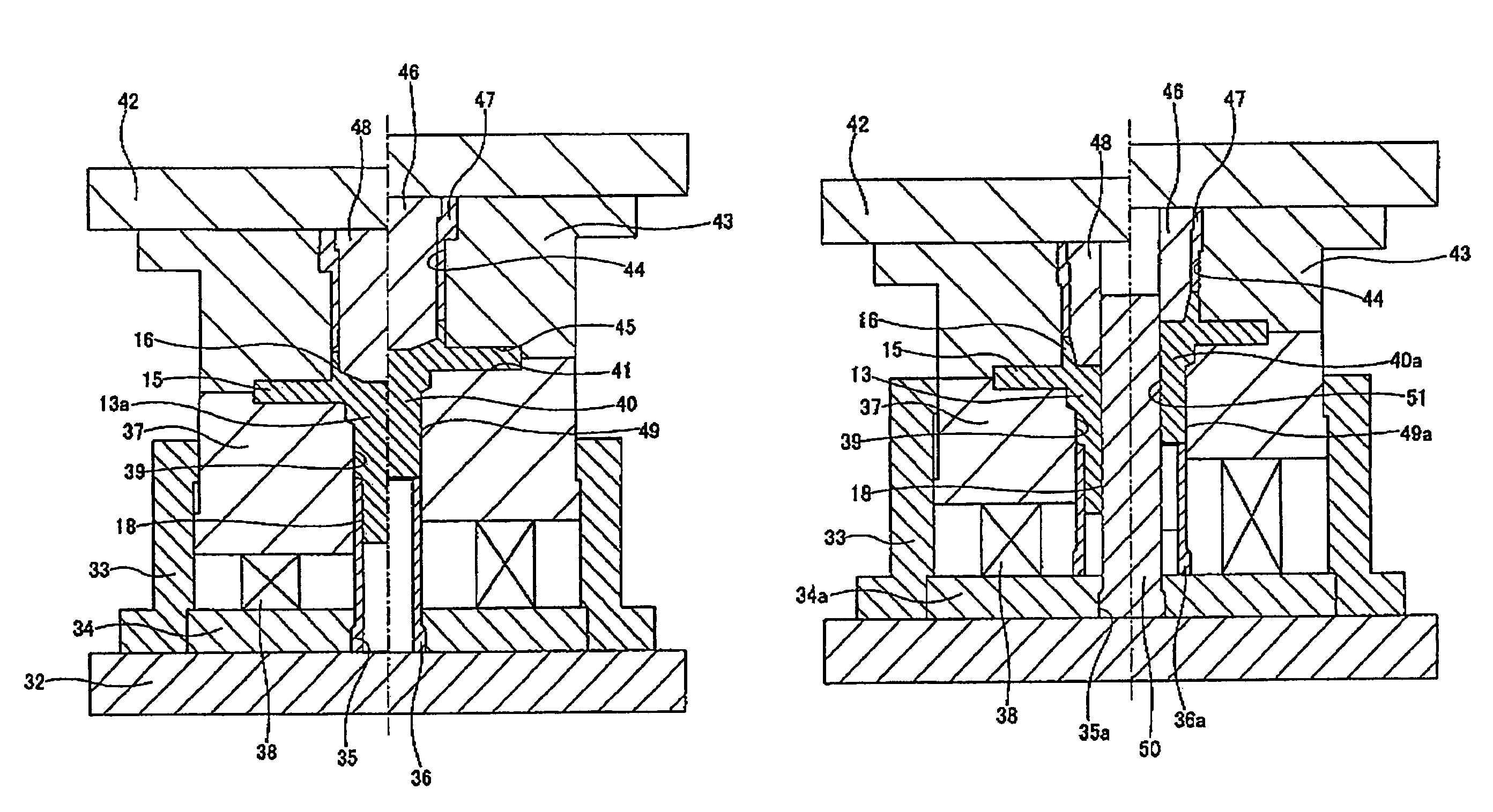
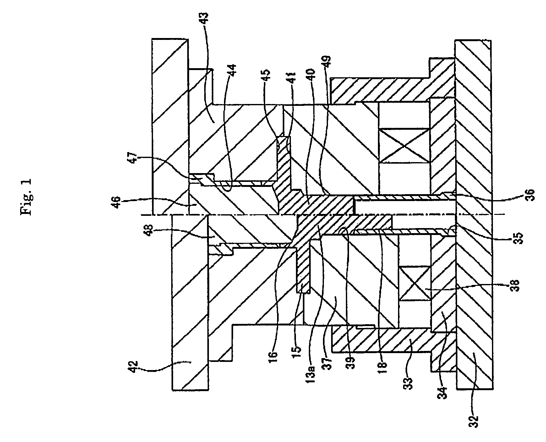
[0048]FIG. 1 shows a first embodiment of the present invention. The purpose of this embodiment is the manufacture of a hub body (bearing ring member) 13a of a rolling bearing unit for wheel support for undriven wheels as shown in FIG. 19 described above. In FIG. 1, the right half of the figure shows the state immediately before starting processing, and the left half shows the state after processing is completed. First, the manufacturing equipment will be explained.

[0049]A holding cylinder 33 is fastened to the top surface of a base 32 that is fastened to the top surface of the table of a press (not shown in the figure). A restraining plate 34 is fastened on the inside of the bottom end section of the holding cylinder 33, and the bottom end section of a cylindrical shaped lower punch 36, which functions as a receiving punch, is supported and fastened inside a center hole 35 in the restraining plate 34. A thick cylindrical shaped lower die 37, which functions as a floating die, is hel...

second embodiment

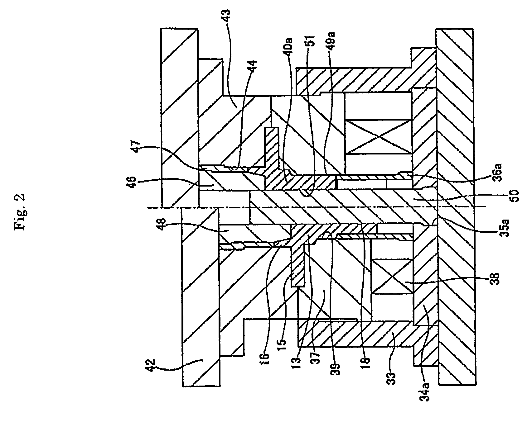
[0059]FIG. 2 shows a second embodiment of the present invention. The purpose of this embodiment is the manufacture of a hub body (bearing ring member) 13 of a rolling bearing unit for wheel support for drive wheels as shown in FIG. 18 and described above. In this embodiment, the base end section (bottom end section) of a circular column shaped mandrel 50 is supported and fastened in the center hole 35a of a retaining plate 34a of the manufacturing apparatus, and the base end section (bottom end section) of a cylindrical shaped lower punch 36 is fastened on the top surface of this retaining plate 34a around the mandrel 50 so that it is concentric with the mandrel 50. Moreover, an intermediate material 40, around whose outer peripheral surface a small-diameter step section 18 is to be formed, is cylindrical shaped having a center hole 51. It is preferred that this center hole 51 be a simple circular hole (a female spline is processed later) in that it will be easier to remove the hub ...


PUM

PropertyMeasurementUnit
outer diameter DAaaaaaaaaaa
diameteraaaaaaaaaa
outer diameteraaaaaaaaaa

Abstract

This invention provided a manufacturing method to process a small-diameter step section 18 on an inside end section of a hub body 13a that comprises an outward facing flange 15 and a positioning cylinder 16 stably and with high precision. In this invention, an intermediate material 40 is pressed between a lower punch 36 and an upper punch 46 with an outer peripheral surface of the intermediate material 40 being held by a lower die 37 and an upper die 43, and then a part of the intermediate material 40 is pressed into the lower punch 36 such that the small-diameter step section 18 is formed by cold plastic working.

Description

FIELD OF THE INVENTION[0001]The present invention relates to a process for manufacturing a bearing ring member of a rolling bearing unit for wheel support.BACKGROUND OF THE INVENTION[0002]The wheel 1 of an automobile, and the rotor 2, which is a rotating member for braking of a disc brake as a braking apparatus, are supported so that they rotate freely by the knuckle 3 of a suspension apparatus using construction as shown in FIG. 8. That is, the outer ring 6 of a hub unit 5 for wheel support is fastened to the circular support holes 4 that are formed in this knuckle 3 by a plurality of bolts 7. On the other hand, the wheel 1 and rotor 2 are connected and fastened to the hub 8 of this hub unit 5 for wheel support by plurality of studs 9 and nuts 10. In addition, a double row of outer raceways 11a, 11b are formed around the inner peripheral surface of the outer ring 6, and a connection flange 12 is formed around the outer peripheral surface of this outer ring 6. This kind of outer rin...

Claims


Application Information

Patent Timeline
Patent Type & Authority Patents(United States)
IPC IPC(8): B21K1/40
CPCF16C33/64F16C2326/02B21K1/40B21J5/02B21K23/04F16C19/186Y10T29/49533Y10T29/49689Y10T29/49636Y10T29/49679
Inventor KOBAYASHI, KAZUTOYASUDA, YUUOOTSUKA, KIYOSHI
Owner NSK LTD
Why Eureka
Try Eureka