Artificial mangrove assembly

a technology of mangroves and mangroves, applied in pisciculture, aquaria, climate change adaptation, etc., can solve the problems of affecting the life of mangroves, affecting the health of mangroves,

Inactive Publication Date: 2014-01-28
SHEPARD III LEE C
View PDF30 Cites 8 Cited by
  • Summary
  • Abstract
  • Description
  • Claims
  • Application Information

AI Technical Summary

Benefits of technology

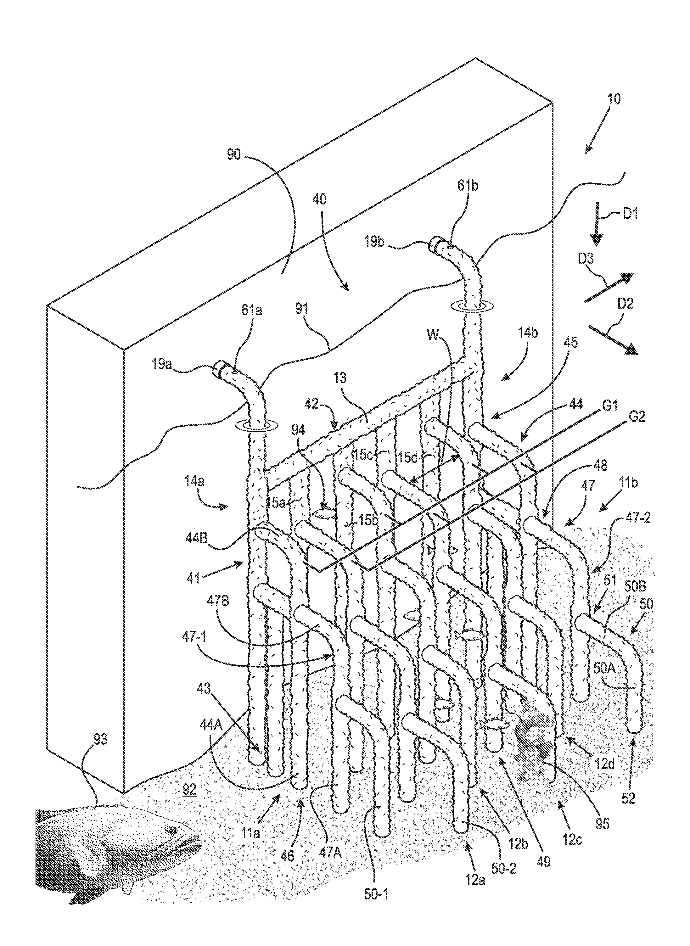
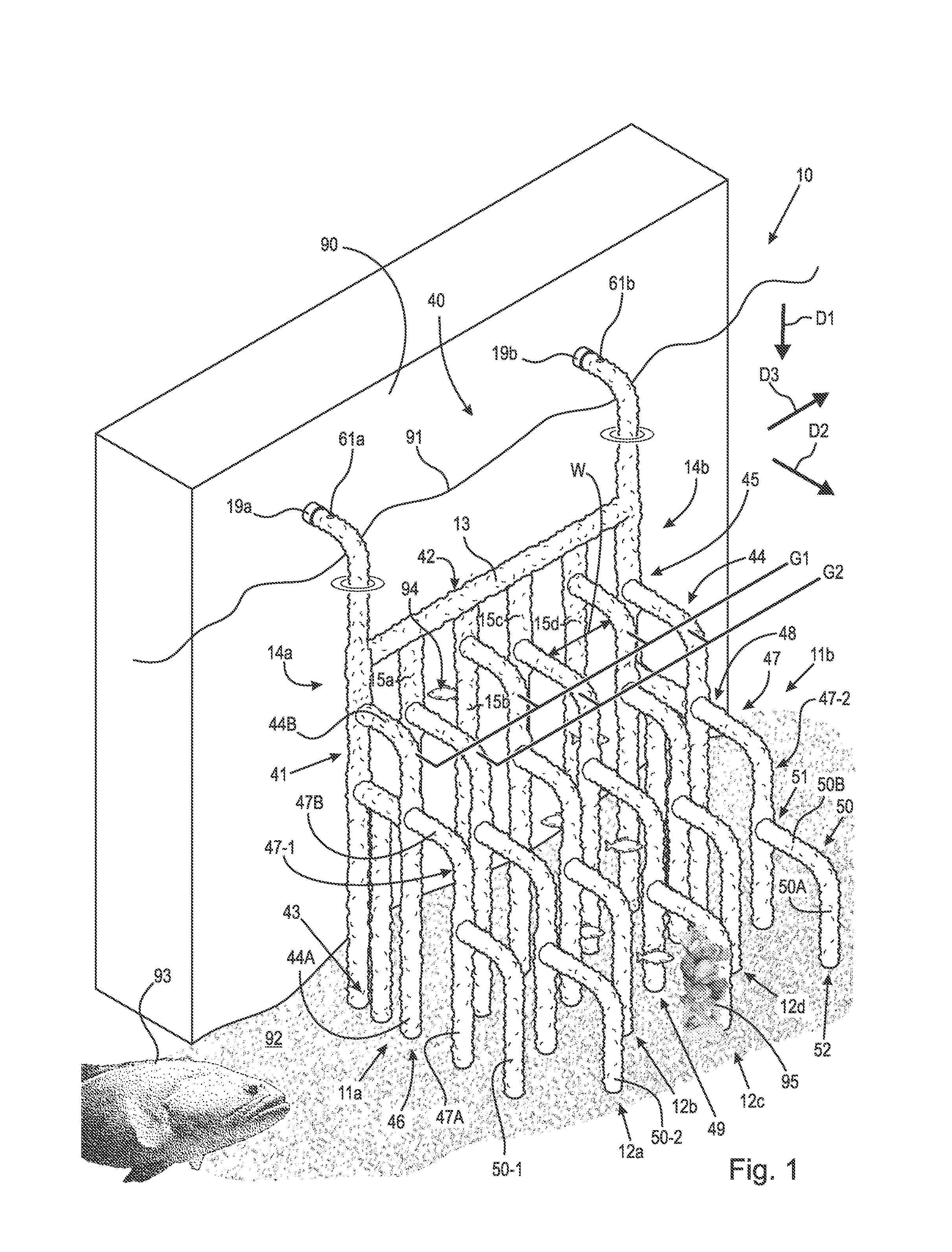
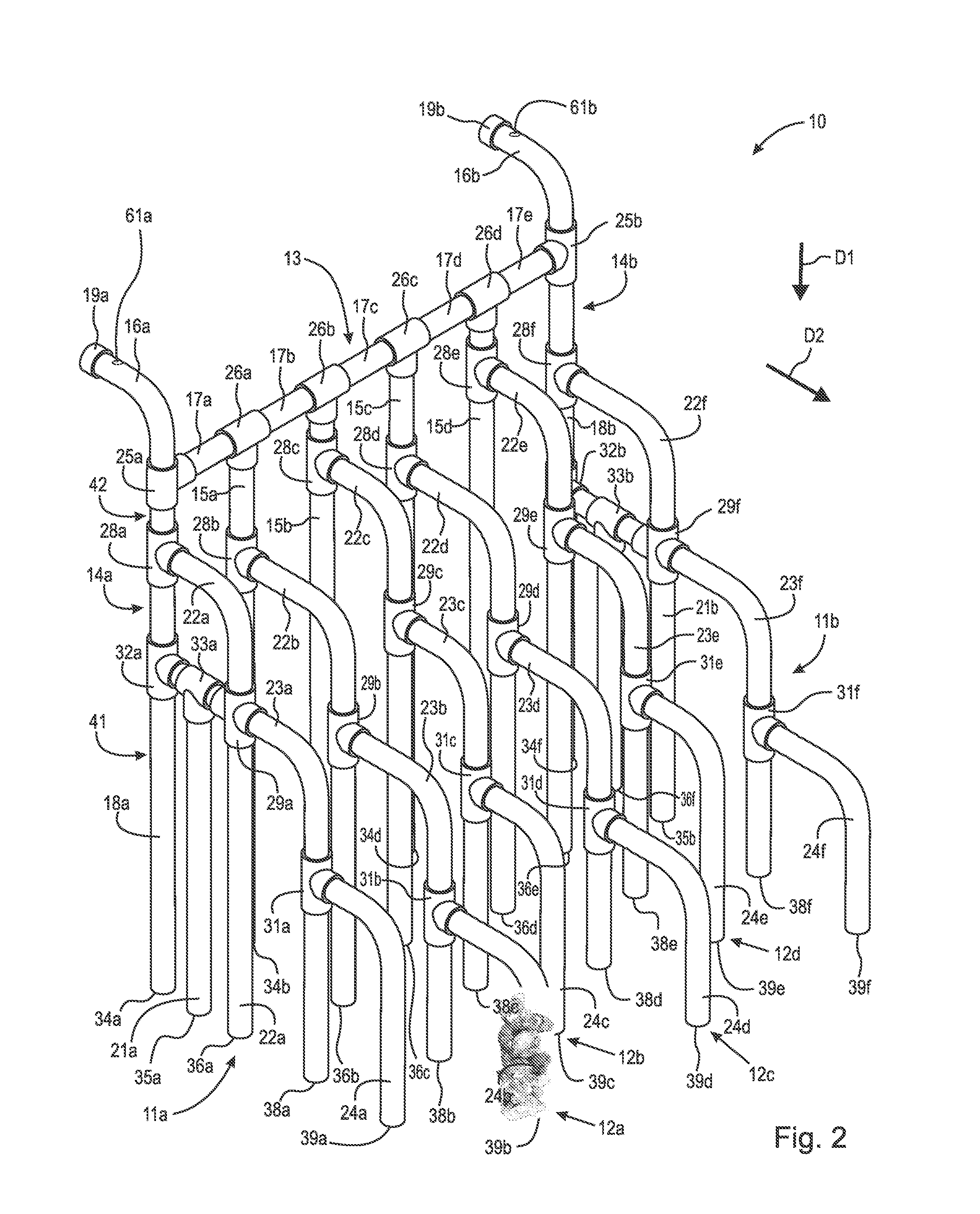
[0004]According to aspects illustrated herein, there is provided an artificial mangrove assembly for providing a habitat for aquatic organisms, including: a mounting assembly arranged for attachment to a surface at least partially submerged in a body of water; and respective pluralities of first and second root elements. Each first root element is fixedly secured to the mounting assembly at a respective first connection point, extends downward in a first direction from the respective first connection point, and includes a respective first distal end arranged to contact a bottom of the body of water. Each second root element is fixedly secured to a respective first root element at a respective second connection point and includes: a respective first portion extending downward in the first direction with respect to the respective second connection point; a respective second portion extending outward with respect to the respective second connection point in the second direction; and a respective second distal end arranged to contact the bottom of the body of water.

Problems solved by technology

The disappearance of mangroves, or deforestation, contributes to declines in fisheries, threats to bird species, erosion and land subsidence, degradation of clean water, salinization of coastal soils, and the release of carbon dioxide into the atmosphere.
Dock pilings and other structures along the coastline provide inadequate protection for marine life from predators.
The synthetic habitat device is problematic because the device provides only a limited amount of shelter space for marine life.
Similarly, the device provides only a limited amount of surface area for colonizing aquatic life.

Method used


Image

  • Artificial mangrove assembly
  • Artificial mangrove assembly
  • Artificial mangrove assembly

Examples


Embodiment Construction

[0016]At the outset, it should be appreciated that like drawing numbers on different drawing views identify identical, or functionally similar, structural root elements of the invention. Moreover, although any methods, devices or materials similar or equivalent to those described herein can be used in the practice or testing of these embodiments, some embodiments of methods, devices, and materials are now described.

[0017]Furthermore, it is understood that this invention is not limited to the particular methodology, materials and modifications described and, as such, may, of course, vary. It is also understood that the terminology used herein is for the purpose of describing particular aspects only, and is not intended to limit the scope of the present invention, which is limited only by the appended claims.

[0018]Unless defined otherwise, all technical and scientific terms used herein have the same meaning as commonly understood to one of ordinary skill in the art to which this inven...


PUM


Abstract

An artificial mangrove assembly, including: a mounting assembly for attachment to a surface at least partially submerged in a body of water; and respective pluralities of first and second root elements. Each first root element is fixedly secured to the mounting assembly at a respective first connection point, extends downward in a first direction from the respective first connection point, and includes a respective first distal end arranged to contact a bottom of the body of water. Each second root element is fixedly secured to a respective first root element at a respective second connection point and includes: a respective first portion extending downward in the first direction with respect to the respective second connection point; a respective second portion extending outward with respect to the respective second connection point in the second direction; and a respective second distal end arranged to contact the bottom of the body of water.

Description

FIELD OF THE INVENTION[0001]The present disclosure broadly relates to an artificial underwater ecosystem assembly, and, more particularly, to an artificial mangrove assembly to provide habitat for flora and fauna and reduce the impact of high-energy wave action on coastal areas.BACKGROUND OF THE INVENTION[0002]Natural mangroves are a type of ecosystem made of various kinds of trees that grow in saline coastal sediment habitats in the tropics and subtropics. Broadly, the term “mangrove” refers to the entire plant assemblage, or mangal, found by depositional coastal environments. The roots of the mangrove provide habitat for marine flora and fauna, such as fish, crustaceans, and birds. Moreover, the roots act as a substrate for marine life colonization, and trap aquatic nutrients for marine life. Naturally occurring mangroves are rapidly disappearing for a number of reasons including climate change, barnacle infestation, weeds, pollution, logging, oil exploration and extraction, shrim...

Claims


Application Information

Patent Timeline
Patent Type & Authority Patents(United States)
IPC IPC(8): A01K61/00
CPCA01K61/006A01K61/00A01K61/70Y02A40/81
Inventor SHEPARD, III, LEE, C.
Owner SHEPARD III LEE C
Why Eureka
Try Eureka