Wideband balun using re-entrant coupled lines and ferrite material

a ferrite material and coupled line technology, applied in the field of baluns, to achieve the effect of good performan

Active Publication Date: 2014-01-28
TTM TECH INC
View PDF11 Cites 2 Cited by
  • Summary
  • Abstract
  • Description
  • Claims
  • Application Information

AI Technical Summary

Benefits of technology

[0019]The present invention generally relates to an electronic component referred to as a “balun,” and specifically addresses a new construction for a balun, as well as new construction methods for constructing baluns. Preferred baluns according to the present invention are designed to operate in the high frequency (RF) spectrum (HF, VHF, UHF, Microwave). Preferred baluns according to the present invention have: (i) good performance over a wide frequency range (a broadband device); (ii) can handle high signal levels (hundreds of Watts); and / or (iii) can be packaged in a volume that is significantly smaller than what is otherwise available today.

Problems solved by technology

Not every ferrimagnetic, non-electrically conductive material will necessarily work.

Method used


Image

  • Wideband balun using re-entrant coupled lines and ferrite material
  • Wideband balun using re-entrant coupled lines and ferrite material
  • Wideband balun using re-entrant coupled lines and ferrite material

Examples


Embodiment Construction

[0055]As a preliminary note, the embodiment(s) of the present invention that are about to be discussed will be generally be baluns with a 1:1 impedance transformation, it will be understood by those of skill in the art that many inventive aspects of the present invention could be applied to baluns having other impedance ratios, such as a 1:4 balun. Also, while it is preferred that the coupled lines be in the form of generally planar strip lines, and, more specifically, in the form of strip lines oriented so that their major surfaces face each other (that is, a broadside orientation), it should be understood that other types of coupled lines and / or other orientations (now known or to be developed in the future) may be possible.

[0056]The present invention recognizes that coupled lines should be designed as physically short as possible while still achieving good balun performance. This shortness will allow for the smallest packaging and lowest insertion loss.

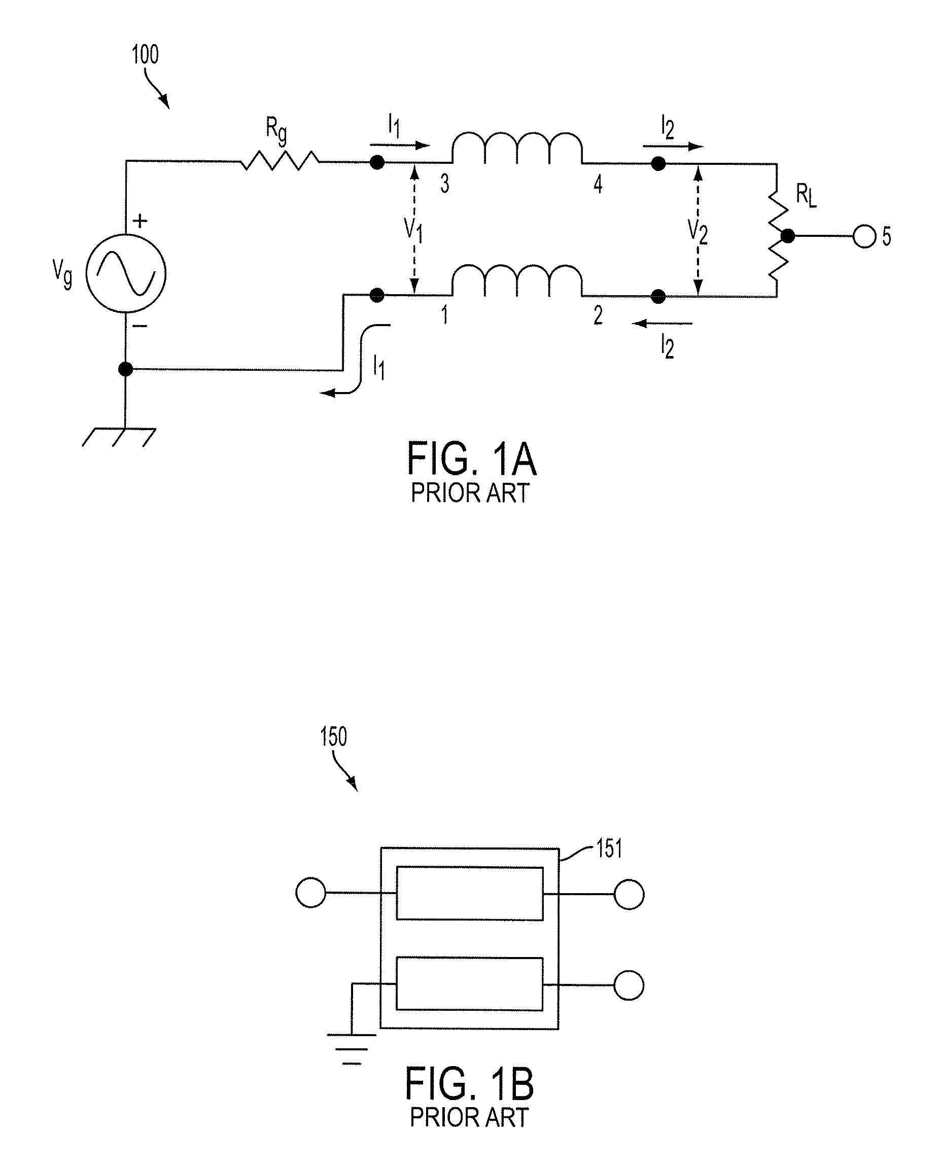
[0057]As shown in schematic...


PUM

PropertyMeasurementUnit
frequencyaaaaaaaaaa
operational power ratingaaaaaaaaaa
operating frequenciesaaaaaaaaaa

Abstract

A Guanella type balun with a conductive enclosure (for example, a re-entrant box) between its coupled lines and the magnetic material enclosing its coupled lines. Some embodiments use coupled strip lines. Some embodiments have dielectric material, such as printed circuit board material inside the re-entrant box along with the coupled strip lines. Preferably, the magnetic material is ferrimagnetic. Some preferred magnetic materials are non-conductive.

Description

RELATED APPLICATION[0001]The present application claims priority to U.S. provisional patent application No. 61 / 375,319, filed on Aug. 20, 2010; all of the foregoing patent-related document(s) are hereby incorporated by reference herein in their respective entirety(ies).BACKGROUND OF THE INVENTION[0002]1. Field of the Invention[0003]The present invention relates to baluns and more particularly to Guanella style baluns.[0004]2. Description of the Related Art[0005]It has long been known that an enclosure of conductive material will block electrical fields. That is, electrical fields inside the enclosure do not leak out and electric fields outside the enclosure do not get inside of the enclosure. The enclosure does not need to be continuous (for example, it may be a mesh) but it must be at least somewhat continuous to substantially block passage of electrical fields in or out of the enclosure. For example, U.S. Pat. No. 3,237,130 (“130 Cohn”) discloses a directional coupler for microwav...

Claims


Application Information

Patent Timeline
Patent Type & Authority Patents(United States)
IPC IPC(8): H01P3/08H03H7/42
CPCH03H7/42H05K1/0243H01P5/10Y10T29/49155
Inventor GERST, CARLMERRILL, JEFFREY C.
Owner TTM TECH INC
Why Eureka
Try Eureka