Hydraulic clutch device

a clutch device and hydraulic technology, applied in the direction of fluid actuated clutches, clutches, non-mechanical actuated clutches, etc., can solve the problems of increasing the binding force of the clip and the difficulty of assembling, so as to improve the workability of assembling the hydraulic clutch device, the binding force of the locking tool can be made smaller, and the effect of easy assembly

Active Publication Date: 2014-02-04
HONDA MOTOR CO LTD +1
View PDF19 Cites 4 Cited by
  • Summary
  • Abstract
  • Description
  • Claims
  • Application Information

AI Technical Summary

Benefits of technology

[0009]According to this configuration, since the locking tool that regulates the movement of the canceller plate is disposed in engagement with the inner peripheral groove of the projection portion in the clutch piston guide so that the locking tool is supported by the inner peripheral groove from the outer peripheral side, the locking tool is not removed by the centrifugal force when the clutch piston guide is rotated. Thus, the binding force of the locking tool can be made smaller, and the workability of assembling of the hydraulic clutch device can be improved.
[0026]In addition, since the thickness of the projection portion is formed thinner than the interval between the end of the clutch piston guide and the locking tool, the operating oil can pass through the notch portion and flow in / out of the hydraulic canceller chamber. Thus, there is no need to particularly provide an oil path through which the operating oil in the hydraulic canceller chamber passes, and the structure can be simplified.

Problems solved by technology

However, in the above prior-art hydraulic clutch device, it is likely that the clip is deformed by a centrifugal force and the clip is removed if a rotation number of the clutch hub is increased, so there is a need to increase a binding force of the clip.
Thus, during an assembling work, the work should be performed against the large binding force of the clip, which causes a problem in workability of assembling.

Method used


Image

  • Hydraulic clutch device
  • Hydraulic clutch device
  • Hydraulic clutch device

Examples


Embodiment Construction

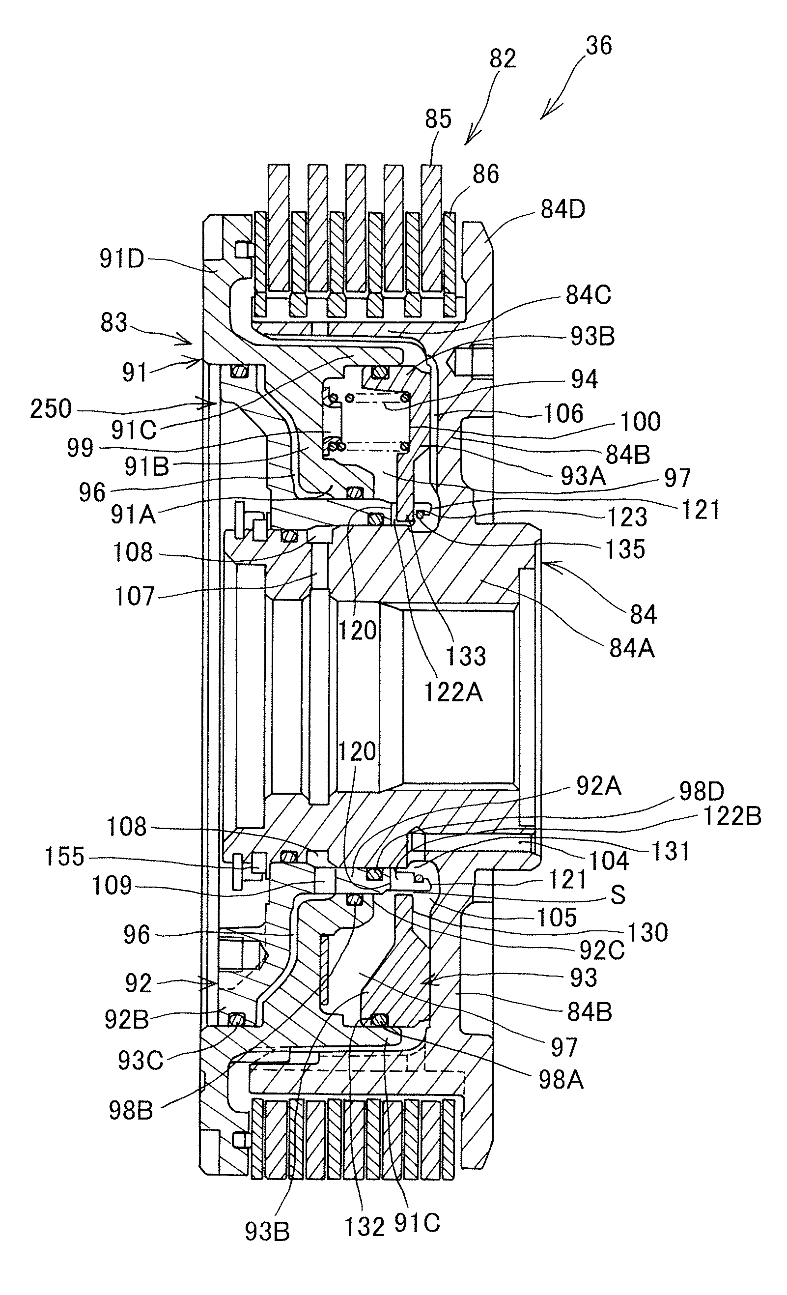
[0036]A hydraulic clutch device according to an embodiment of the present invention will be described below referring to the attached drawings.

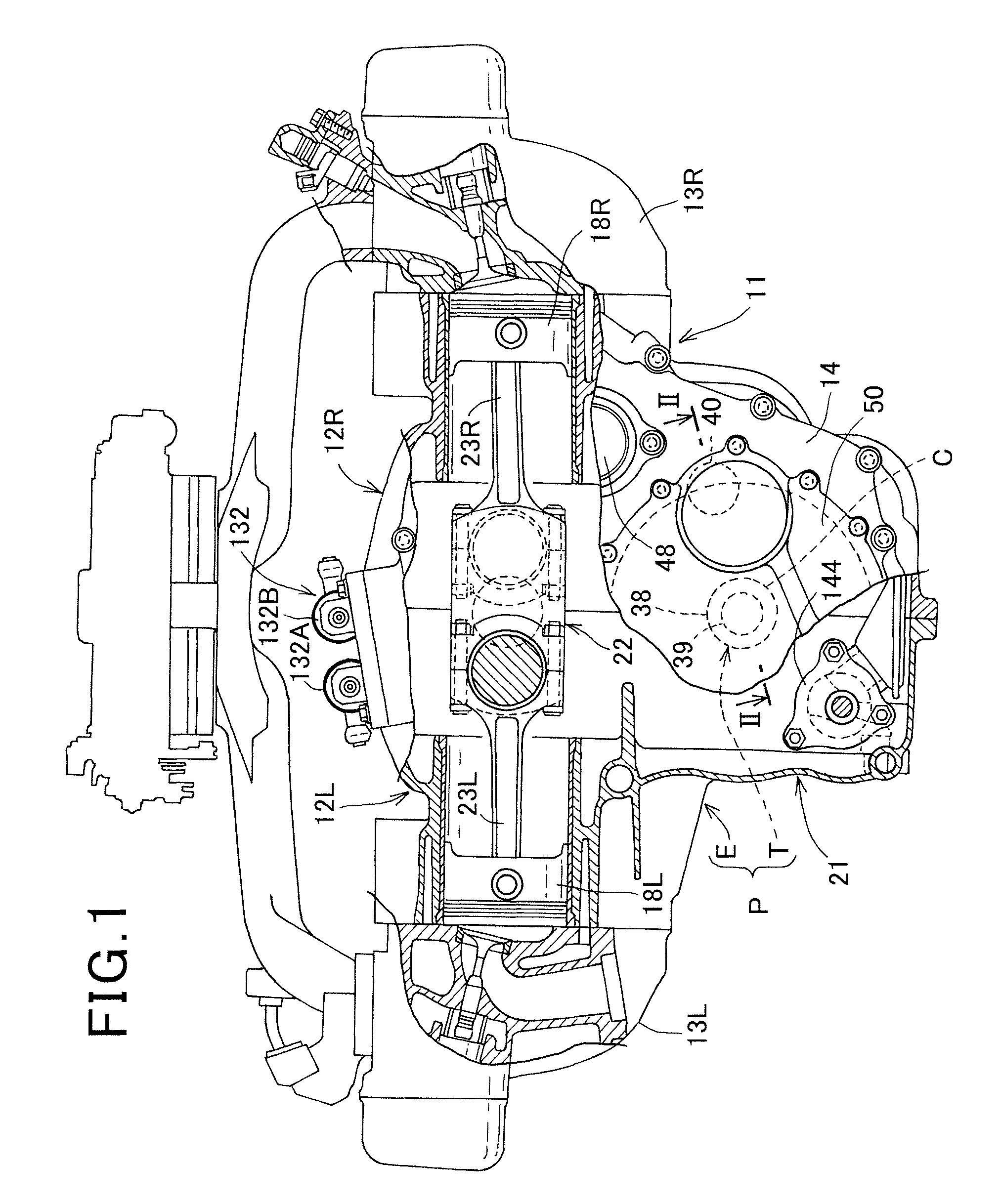
[0037]FIG. 1 is a partially cutaway rear view of a power unit according to an embodiment of the present invention.

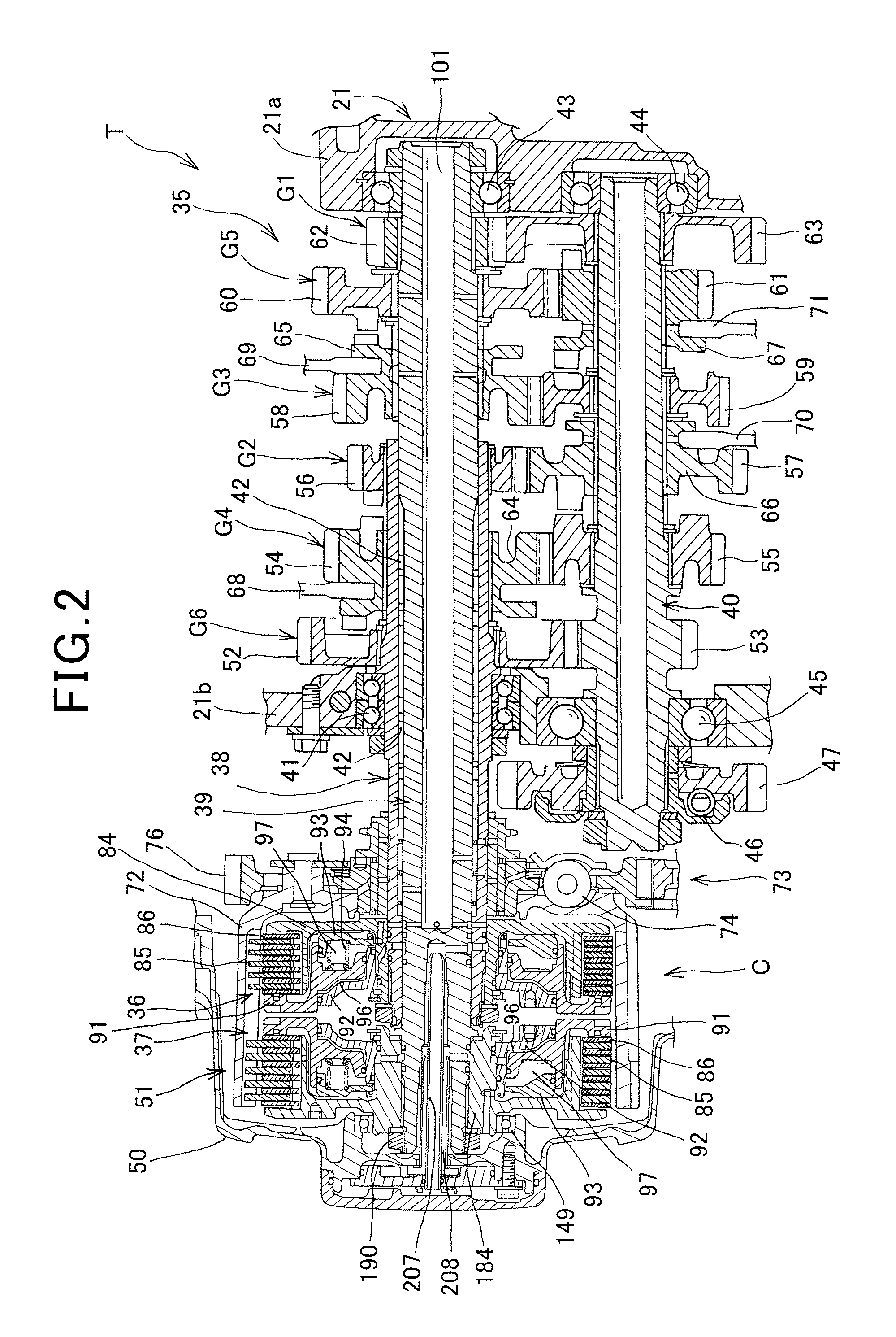
[0038]As shown in FIG. 1, a power unit P mounted on a motorcycle, for example, has a multi-cylinder horizontally opposed engine E, which is a four-cycle engine, and a transmission T that changes power of the engine E. The transmission T has a hydraulic clutch mechanism C.

[0039]An engine main body 11 of the engine E is provided with a left engine block 12L arranged on the left side in a state oriented to the front in the driving direction of the motorcycle, a right engine block 12R arranged on the right side in a state oriented to the front in the driving direction, left and right cylinder heads 13L and 13R joined to both outer ends of the left and right engine blocks 12L and 12R, and a rear case 14 joined to the left and right eng...


PUM


Abstract

In a first hydraulic clutch device 36 provided with a first clutch inner 84, a pressure bearing plate portion 84D disposed on the first clutch inner 84 opposing driving and driven friction plates 85 and 86, a clutch piston 91 that is consecutively disposed to a pressurizing plate portion 91D and moves to the side to pressurize the driving and driven friction plates 85 and 86 in accordance with an increase in a hydraulic pressure in a control hydraulic chamber 96, a piston guide 92 that forms a control hydraulic chamber 96 between itself and the clutch piston 91, and a canceller plate 93 that forms a hydraulic canceller chamber 97 on the side opposite to the control hydraulic pressure chamber 96, a projection portion 133 of the canceller plate 93 and a notch portion 122 disposed in the piston guide 92 and engaged with the projection portion 133 are engaged with each other and assembled, and a clip 135 that is engaged with an engagement groove 123 of the notch portion 122 and regulates axial movement of the canceller plate 93 is disposed.

Description

INCORPORATION BY REFERENCE[0001]The present application claims priority under 35 U.S.C. §119 to Japanese Patent Application No. 2009-270262 filed on Nov. 27, 2009. The contents of the applications are incorporated herein by reference in its entirety.BACKGROUND OF THE INVENTION[0002]1. Field of the Invention[0003]The present invention relates to a hydraulic clutch device provided with a canceller plate that forms a hydraulic canceller chamber.[0004]2. Description of the Related Art[0005]Hitherto, in a hydraulic clutch device, a canceller plate in which a hydraulic canceller chamber is formed between the canceller plate and a clutch piston slidably fitted in a clutch hub is locked by the clutch hub with a clip engaged with an outer periphery of the clutch hub (for example, JP-A-8-277852).[0006]However, in the above prior-art hydraulic clutch device, it is likely that the clip is deformed by a centrifugal force and the clip is removed if a rotation number of the clutch hub is increased...

Claims


Application Information

Patent Timeline
Patent Type & Authority Patents(United States)
IPC IPC(8): F16D25/08
CPCF16D25/0638F16D25/10F16D2021/0661F16D25/12F16D2021/0692F16D21/06
Inventor OGASAWARA, ATSUSHIWATANABE, JUNYATSUCHIYA, MASAHIKOOOISHI, AKIOKATAOKA, MAKOTOYOSHIMOTO, KATSU
Owner HONDA MOTOR CO LTD
Why Eureka
Try Eureka