Vehicle seat reclining apparatus

a vehicle seat and apparatus technology, applied in the field of vehicles, can solve the problems of small regulating member, prone to bend, decrease in lock strength, etc., and achieve the effects of increasing the axial length of the cylindrical portion, reducing lock strength, and increasing the plate thickness

Inactive Publication Date: 2014-02-04
TF METAL CO LTD
View PDF11 Cites 12 Cited by
  • Summary
  • Abstract
  • Description
  • Claims
  • Application Information

AI Technical Summary

Benefits of technology

[0004]However, the regulating member is small in the thickness in the radial direction, and hence liable to bend. Therefore, when axial load is applied to the cover member, the axial displacement of the cover member may be increased, so that the reclining mechanism tends to cause unsteady movement of the seat back in the left and right direction, and to cause a decrease of the lock strength. In the case of the patent document 2, the cylindrical portion of the cover member is formed by half blanking of press forming, and the cover member is required to have a greater plate thickness to increase the axial length of the cylindrical portion. However, the increase of the thickness of the cover member causes an increase of the size of the cover member in the radial direction, and an increase of the size of the entire reclining mechanism.
[0006]Therefore, it is an object of the present invention to provide a seat reclining apparatus adequate for increasing the strength and reducing the size of the seat reclining apparatus.

Problems solved by technology

However, the regulating member is small in the thickness in the radial direction, and hence liable to bend.
Therefore, when axial load is applied to the cover member, the axial displacement of the cover member may be increased, so that the reclining mechanism tends to cause unsteady movement of the seat back in the left and right direction, and to cause a decrease of the lock strength.
However, the increase of the thickness of the cover member causes an increase of the size of the cover member in the radial direction, and an increase of the size of the entire reclining mechanism.
However, in this mechanism, the cover member is liable to rotate unsteadily relative to the frame member because the cover member is held by the sliding contact with the regulating member.
Moreover, sparks (such as sputter) produced by the laser welding are liable to enter the sliding contact portion between the cover member and the regulating member, and hence to deteriorate the sliding smoothness.

Method used


Image

  • Vehicle seat reclining apparatus
  • Vehicle seat reclining apparatus
  • Vehicle seat reclining apparatus

Examples


first embodiment

[0014

[0015]A vehicle seat shown in FIG. 6 includes a seat cushion 2 serving as a seat portion on which a seat occupant sits, and a seat back 3 connected with seat cushion 2 in such a rotatable manner that seat back 3 can rotate back and forth in the longitudinal direction of the vehicle. In this example, a frame member 5 serving as a base member is connected with seat cushion 2 through a base plate 4. A cover or lid member 7 (not shown in FIG. 6) serving as a rotation member is connected with seat back 3 through an arm plate 6. A spring (not shown) is provided for urging the seat back 3 in a leftward direction which is a forward direction toward the front of the vehicle, relative to the seat cushion 2.

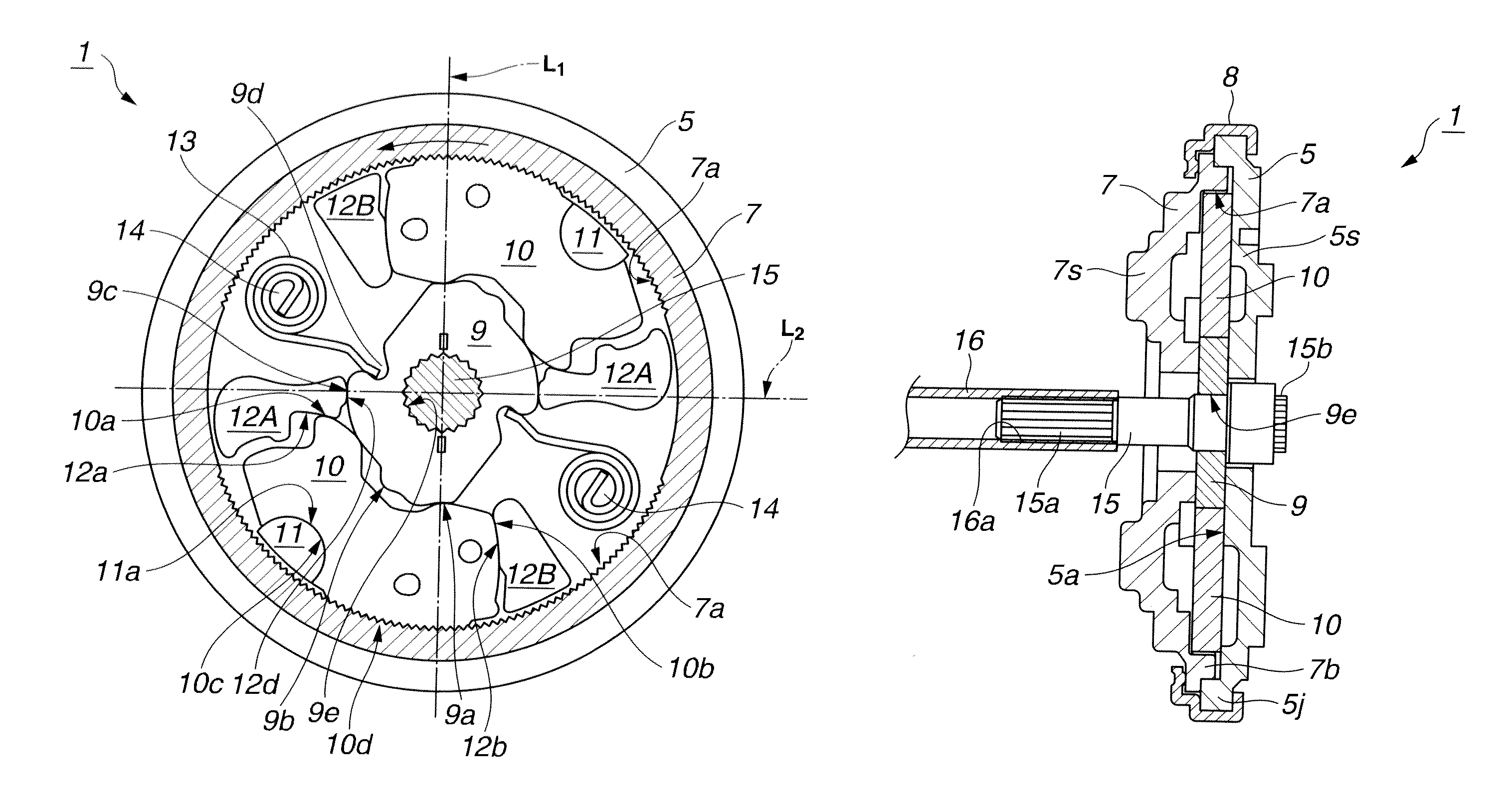
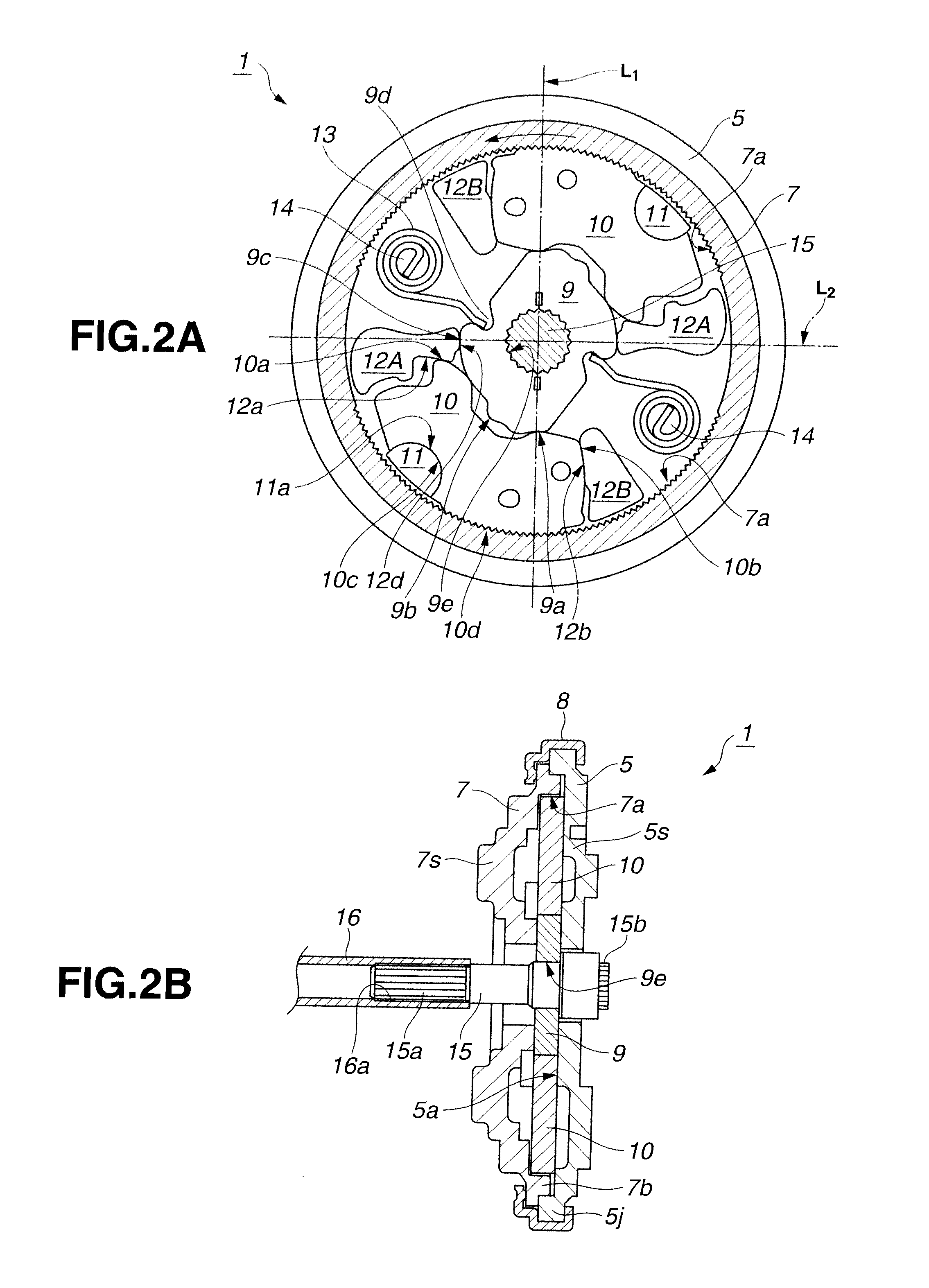
[0016]The frame member 5 and cover member 7 are constituent members of a vehicle seat reclining mechanism 1 shown in FIGS. 2A and 2B, as explained below. As shown in FIG. 2B, frame member 5 includes a circular recess 5a formed by half blanking of a circular plate with a press. Frame me...

second embodiment

[0041

[0042]FIG. 3 shows a vehicle seat reclining mechanism according to a second embodiment of the present invention. The second embodiment is basically the same as the first embodiment so that repetitive explanation is omitted by using the same reference numerals for the same parts. The following explanation is directed to feature of the second embodiment different from the first embodiment.

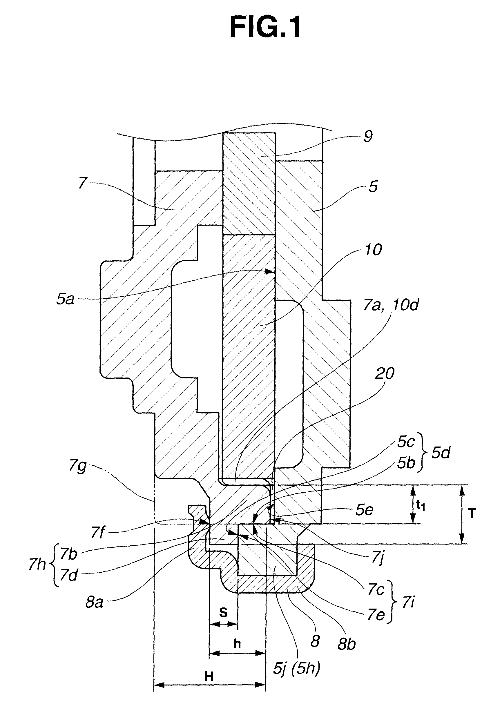
[0043]As shown in FIG. 3, the end surface 7j of the cylindrical portion 7b of cover member 7 is put in sliding contact with the bottom surface (confronting center wall surface) 5e of circular recess 5a of frame member 5. Thus, the end surface 7j is used as the (flat) sliding side surface. The first side surface 7e of flange 7d is spaced axially from the end surface 5c (confronting surface) of rim portion 5j of frame member 5 by a clearance 21. This clearance 21 is set to have a dimension (such as an axial dimension in the axial direction) to prevent contact between surfaces 7e and 5c even in the...

third embodiment

[0046

[0047]FIG. 4 shows a vehicle seat reclining mechanism according to a third embodiment of the present invention. The third embodiment is basically the same as the second embodiment so that repetitive explanation is omitted by using the same reference numerals for the same parts. The following explanation is directed to feature of the third embodiment different from the second embodiment.

[0048]The seat reclining mechanism shown in FIG. 4 is different from the mechanism shown in FIG. 3 according to the second embodiment only in the structure connecting the first side portion 8b of holder 8 (regulating member) to the outer circumferential portion 5h(5j) of frame member 5 (base member). The first side portion 8b of holder 8 of FIG. 4 extends straight in the axial direction and has no first side radial wall extending radially inwards on the first (right) side of outer circumferential portion 5h(5j) of frame member 5 to clamp the outer circumferential portion 5h (5j), unlike the first...


PUM


Abstract

A vehicle seat reclining apparatus comprises a base member to be connected to one of a seat cushion and a seat back, a rotation member which is to be connected to the other of the seat cushion and seat back, which is arranged to rotate relative to the base member and which includes an internal gear, a regulating member to regulate axial movement of the rotation member relative to the base member, and a locking setup which includes an external gear and which is arranged to move between a lock position to engage the external gear with the internal gear and an unlock position for disengagement. The base member includes an outer circumferential portion defining a circular recess, the rotation member includes an outer circumferential portion including a cylindrical portion fit rotatably in the outer circumferential portion of the base member. The outer circumferential portion of the rotation member further includes a flange portion which projects radially outwards from the cylindrical portion, which is placed axially between the regulating member and the outer circumferential portion of the base member and which includes a side surface facing away from the base member and servings as a sliding regulation surface set in sliding contact with the regulating member.

Description

BACKGROUND OF THE INVENTION[0001]The present invention relates to apparatus for reclining a vehicle seat designed to increase the strength and reduce the size.[0002]A patent document 1 (JP2008-18108A) discloses a vehicle seat reclining apparatus including a frame member connected with one of a seat cushion and a seat back pivotally connected with the seat cushion, a cover or lid member which is connected with the other of the seat cushion and seat back and which is arranged to rotate relative to the frame member, and a regulating member regulating axial movement of the cover member relative to the frame member. This seat reclining apparatus further includes a lock tooth member for locking and unlocking the relative rotation of the cover member relative to the frame member, and a cam member for shifting the lock tooth member to a lock position or an unlock position.[0003]In the case of vehicle collision, a great force is applied to rotate the seat back violently toward the front of t...

Claims


Application Information

Patent Timeline
Patent Type & Authority Patents(United States)
IPC IPC(8): B60N2/235
CPCB60N2/2356B60N2/2362
Inventor SUZUKI, DAISUKEIGUCHI, DAISUKEMASE, FUMISATO
Owner TF METAL CO LTD
Why Eureka
Try Eureka