Method and apparatus of compensating image in a backlight local dimming system

a local dimming and compensating image technology, applied in the field of backlight local dimming, can solve the problems of reducing image quality, consuming more power, and no help in reducing power consumption, so as to reduce the required area of hardware circuitry, reduce computation amount, and improve image quality

Active Publication Date: 2014-02-04
ORISE TECH CO LTD
View PDF3 Cites 3 Cited by
  • Summary
  • Abstract
  • Description
  • Claims
  • Application Information

AI Technical Summary

Benefits of technology

[0010]The object of the present invention is to provide a method and apparatus of compensating image in a backlight local dimming system, which can reduce the amount of computation, reduce the required area of hardware circuitry, and improve the image quality.

Problems solved by technology

The display of a dark frame is achieved by reducing the transmittance of liquid crystal, which has no help for reducing the power consumption.
Further, the developing LCD devices trend to a large size, so the frames to be displayed require higher brightness, which consumes more power.
A typical backlight local dimming can increase the frame contrast and reduce the power consumption, but the inappropriate backlight decision and image compensation may reduce the image quality, including color washout, ripples, no control of highlight detail, flickers, and inappropriate backlight on dark and light frames.

Method used


Image

  • Method and apparatus of compensating image in a backlight local dimming system
  • Method and apparatus of compensating image in a backlight local dimming system
  • Method and apparatus of compensating image in a backlight local dimming system

Examples


Embodiment Construction

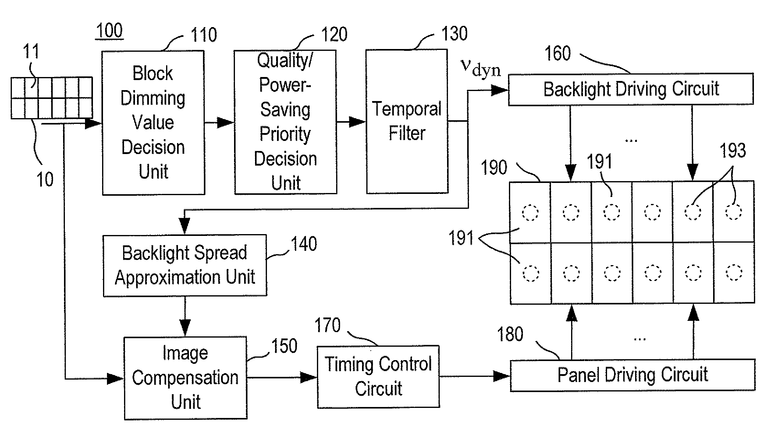
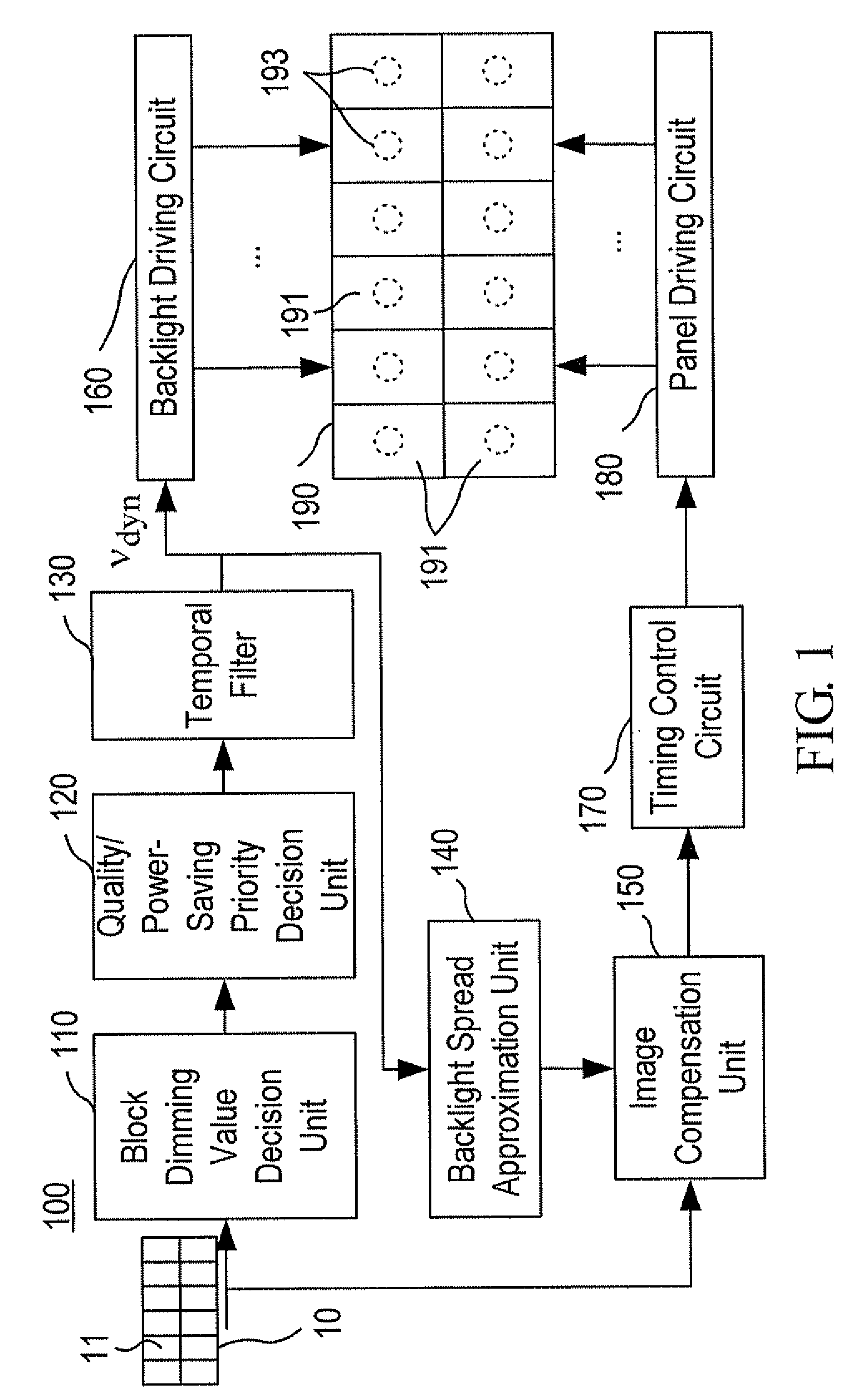
[0019]FIG. 1 is a block diagram of an apparatus 100 of compensating image in a backlight local dimming system in accordance with an embodiment of the invention. In FIG. 1, the apparatus 100 is used in a liquid crystal display (LCD) device. The LCD panel 190 of the LCD device is implemented with a plurality of backlight sources 193 in a matrix arrangement at the back side of the LCD panel 190. The image 10 displayed on the LCD panel 190 is divided into a plurality of image blocks 11 respectively corresponding to the backlight sources 193. Namely, the LCD panel 190 includes a plurality of blocks 191 arranged in a matrix form that correspond to the image blocks 11 for displaying the image, and further correspond to the backlight sources 193, respectively. Each of the backlight sources 193 is driven and controlled by a backlight driving circuit 160 to thus provide a light required for displaying on each block 191 of the LCD panel 190.

[0020]As shown in FIG. 1, the LCD panel 190 is divide...


PUM


Abstract

An apparatus compensates image in a backlight local dimming system for estimating pixels of the image after backlight spreading of a plurality of backlight sources in the backlight local dimming system. The apparatus includes a block dimming value decision unit, a quality / power-saving priority decision unit, a temporal filter, a backlight spread approximation unit, and an image compensation unit. The block dimming value decision unit calculates an average value, a maximum value and a initial value for each image block. The quality / power-saving priority decision unit generates a backlight control signal based on the average value, the initial value, and two thresholds. The temporal filter adaptively generates a backlight pulse width modulation signal based on the backlight control signal. The backlight spread approximation unit generates a backlight spread image based on the backlight pulse width modulation signal. The image compensation unit compensates the image based on the backlight spread image.

Description

CROSS REFERENCE TO RELATED APPLICATION[0001]This application claims the benefits of the Taiwan Patent Application Serial Number 100124619, filed on Jul. 12, 2011, the subject matter of which is incorporated herein by reference.BACKGROUND OF THE INVENTION[0002]1. Field of the Invention[0003]The present invention relates to the technical field of backlight local dimming and, more particularly, to a method and apparatus of compensating image in a backlight local dimming system.[0004]2. Description of Related Art[0005]Multiple backlight sources are typically used in the current liquid crystal display (LCD) device for controlling a plurality of display areas of the LCD device to save the power. The backlight local dimming indicates that the backlight sources of the LCD device are adjusted according to the image brightness, but not in a state of full brightness.[0006]Typically, the backlight sources of the LCD device are at full brightness. The display of a dark frame is achieved by reduc...

Claims


Application Information

Patent Timeline
Patent Type & Authority Patents(United States)
IPC IPC(8): G09G3/36
CPCG09G3/34G09G5/02G09G5/10G09G3/3426G09G2320/0247G09G2340/06G09G2320/064G09G2330/021G09G2360/16G09G3/3611G09G2320/0646G09G2320/0653
Inventor CHANG, CHIH-KAIWU, YU-LI
Owner ORISE TECH CO LTD
Why Eureka
Try Eureka