Interferometric technique for measuring patterned sapphire substrates

a sapphire substrate and interferometric technology, applied in the field of vertical scanning interferometry (vsi) for surface characterization, can solve the problems of total internal reflection, electrical shorts, light is therefore reflected back and lost into the device, etc., and achieves the effect of improving the map of the feature top surface and high reliability

Active Publication Date: 2014-02-04
BRUKER NANO INC
View PDF3 Cites 18 Cited by
  • Summary
  • Abstract
  • Description
  • Claims
  • Application Information

AI Technical Summary

Benefits of technology

[0017]According to another aspect of the invention, a fringe order map of the feature regions is obtained from the height map. Inasmuch as the height profile of a surface is often obtained by adding phase data to a corresponding fringe-order map, in such cases the fringe-order map is readily available for the invention simply by subtracting the phase data from the corresponding height map produced thereby. The fringe-order map is then analyzed to determine the fringe order that is most likely to be correct for the top-region data isolated with the mask. For example, the simple

Problems solved by technology

This difference produces total internal reflection at the device-air interface and light is therefore reflected back and lost into the device.
The height of the PSS structures is particularly crucial because deviations from the target value affects efficiency and wavelength uniformity, and can even cause electrical shorts if the features penetrate the active layer.
However, LED manufacturers process hundreds to thousands of PSS substrates daily and their throughput requires fast, accurate, and non-destructive 3D surface metrology, which is not compatible with either SEM or AFM utilization.
However, in practice scanner steps are not exactly constant and cannot be determined precisely by calibration.
However, as one skilled in the art will readily appreciate, the width and especially the height measurements of the typical PSS feature, as well as similar structures in other surfaces, present a parti

Method used


Image

  • Interferometric technique for measuring patterned sapphire substrates
  • Interferometric technique for measuring patterned sapphire substrates
  • Interferometric technique for measuring patterned sapphire substrates

Examples


Embodiment Construction

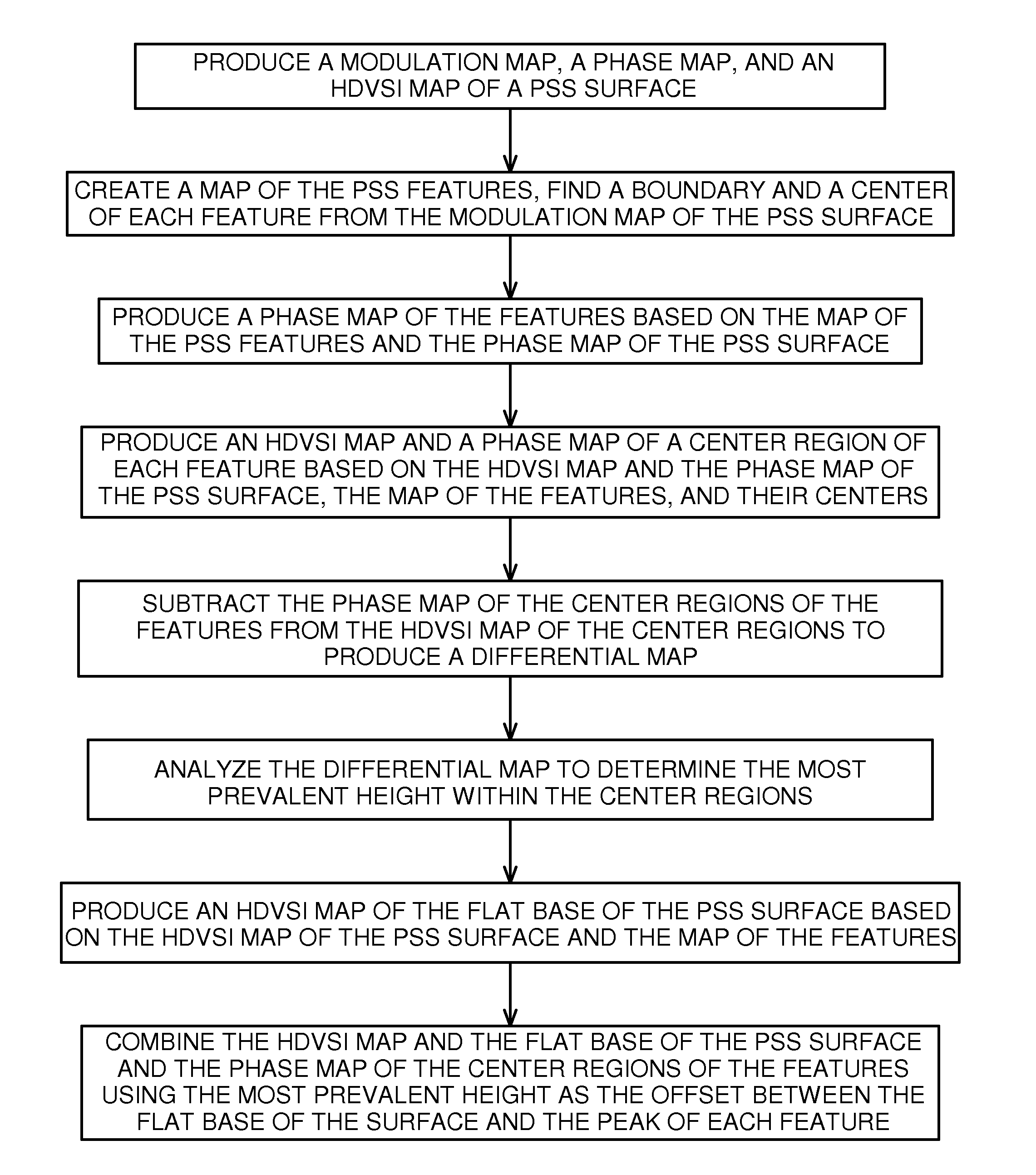
[0045]Those skilled in the art recognize the direct and precise correlation between phase and height with regard to interferometric measurements. Therefore, phase and height, as well as phase data and height data, and also phase map and height map, are used interchangeably in the description that follows without regard to the details of calculation. All operations, such as the subtraction of one map from another, are intended to be performed on the same basis even though not particularly so pointed out in the disclosure. Similarly, the description refers to figures depicting phase maps, but it is understood that such images are only visual representations of phase maps, the actual phase values being represented by gray-scale contrast in the figures, darker regions corresponding to smaller phase values. The terms “patterned feature,”“feature,”“bump” and “protrusion” are used interchangeably in this description to refer to each of the three dimensional structures formed on an otherwis...


PUM


Abstract

A patterned sapphire substrate is measured from a fine phase map and a coarser height map of the sample. The boundaries of the PSS features are identified by finding the locations of minimum contrast in the modulation map of the substrate and are used to produce a height map of the substrate base and a phase map of center regions of the features. A fringe-order map of the features with respect to the base is used to identify the most prevalent fringe order of pixels in the center-regions of the features. That fringe order is adopted as the correct offset between corresponding pixels in the phase map of the center regions of the features and the base of the substrate. A complete map of the substrate is thus obtained by combining the phase map of the features with the height map of the substrate with an offset equal to the fringe order produced by the invention.

Description

BACKGROUND OF THE INVENTION[0001]1. Field of the Invention[0002]This invention relates in general to vertical-scanning interferometry (VSI) for surface characterization. In particular, it relates to a statistical approach applied to determine the fringe order of phase data for measuring uniform micro-features in a sample, such as in patterned sapphire substrates (PSSs) of light emitting diodes (LEDs).[0003]2. Description of the Related Art[0004]The high-brightness LED (HB-LED) industry is experiencing rapid growth as a result of demand for applications in televisions and computer displays, automotive lighting, mobile-phone and other hand-held device displays, and as a more efficient solution for general residential and commercial lighting. Each of these applications requires end products that exhibit tightly controlled efficiency and color, with center wavelength variation of no more than 4 nanometers, so as to be undetectable by the human eye. Optical interferometric profilometry i...

Claims


Application Information

Patent Timeline
IPC IPC(8): G01B11/02
CPCG01B11/02G01B11/2441G01B9/0203G01B9/0209G01B11/0608
Inventor CHEN, DONG
Owner BRUKER NANO INC
Why Eureka
Try Eureka