
Heat-power conversion magnetism devices

a technology of conversion magnetism and heat-power, which is applied in the direction of generator/motor, light and heating apparatus, machine operation mode, etc., can solve the problems of low conversion efficiency, long time-consuming and laborious, and the energy remaining too low

Inactive Publication Date: 2014-02-11
DELTA ELECTRONICS INC
View PDF13 Cites 3 Cited by
  • Summary
  • Abstract
  • Description
  • Claims
  • Application Information

AI Technical Summary

Benefits of technology

The invention introduces a new technology for converting low-temperature heat sources into useful power. This technology does not use electric conductor coils for power generation and has high thermal efficiency. The invention uses magneto caloric effect material, which is a special material that can change its magnetic properties depending on its temperature. This material is placed between a magnet and a sleeve or placed between a magnet and a core, and its magnetic poles are arranged in different ways to achieve the desired magnetic properties. The technical effects of this invention include converting low-temperature heat sources into practical power, simplifying the design of rotation magnetic mechanisms, and having high thermal efficiency.

Problems solved by technology

Converting thermal energy into power had a long period of time in human history.
However, the efficiency of conversion is still very low.
After power conversion, the remained energy becomes too low so that the temperature thereof is usually below 200° C. and mostly below 100° C. Such kind of low-grade energy cannot be utilized by most of the thermal engine available today.
Flat panel of sunshine collector can convert solar energy into hot thermal energy very efficiently (>90%) and cost effectively, but the thermal energy density is very low.
For near room temperature magnetic refrigeration was not able to achieve until 1976.
Although those prior arts give some great ideas of how to change the thermal energy into the mechanical work or electrical power but it never come to realization.
It requires huge amount of energy to rise the temperature up to the Curie temperature, and efficiency is low.
Also the armature moves forward and backward like a pendulum, which is not an efficient way for power generation.
The problem of electric conductor coil is that the power generation of the coil strongly depends on the magnetic flux changing frequency.
Being under such low operation frequency will limit the electrical power output of electric conductor coil and waste large amount of MCEM to convert enough power.
However it is difficult to utilize all the magnetic flux generated by the magnet, and only a part of the magneto caloric ring is attracted by the magnet, thus the mechanical torque output is relative low.
Also how to prevent the leakage of the refrigerant between the heat exchanger and the rotary magneto caloric ring became a very difficult issue.
Although such arrangement can create the maximum thermal effect of the MCEMs, but it also leads to extra problem.
The static torque is also large and requires more driving power to move the magnetic field away from the MCEMs.

Method used


Image

  • Heat-power conversion magnetism devices
  • Heat-power conversion magnetism devices
  • Heat-power conversion magnetism devices

Examples


Embodiment Construction

[0059]The following description is of the best-contemplated mode of carrying out the invention. This description is made for the purpose of illustrating the general principles of the invention and should not be taken in a limiting sense. The scope of the invention is best determined by reference to the appended claims.

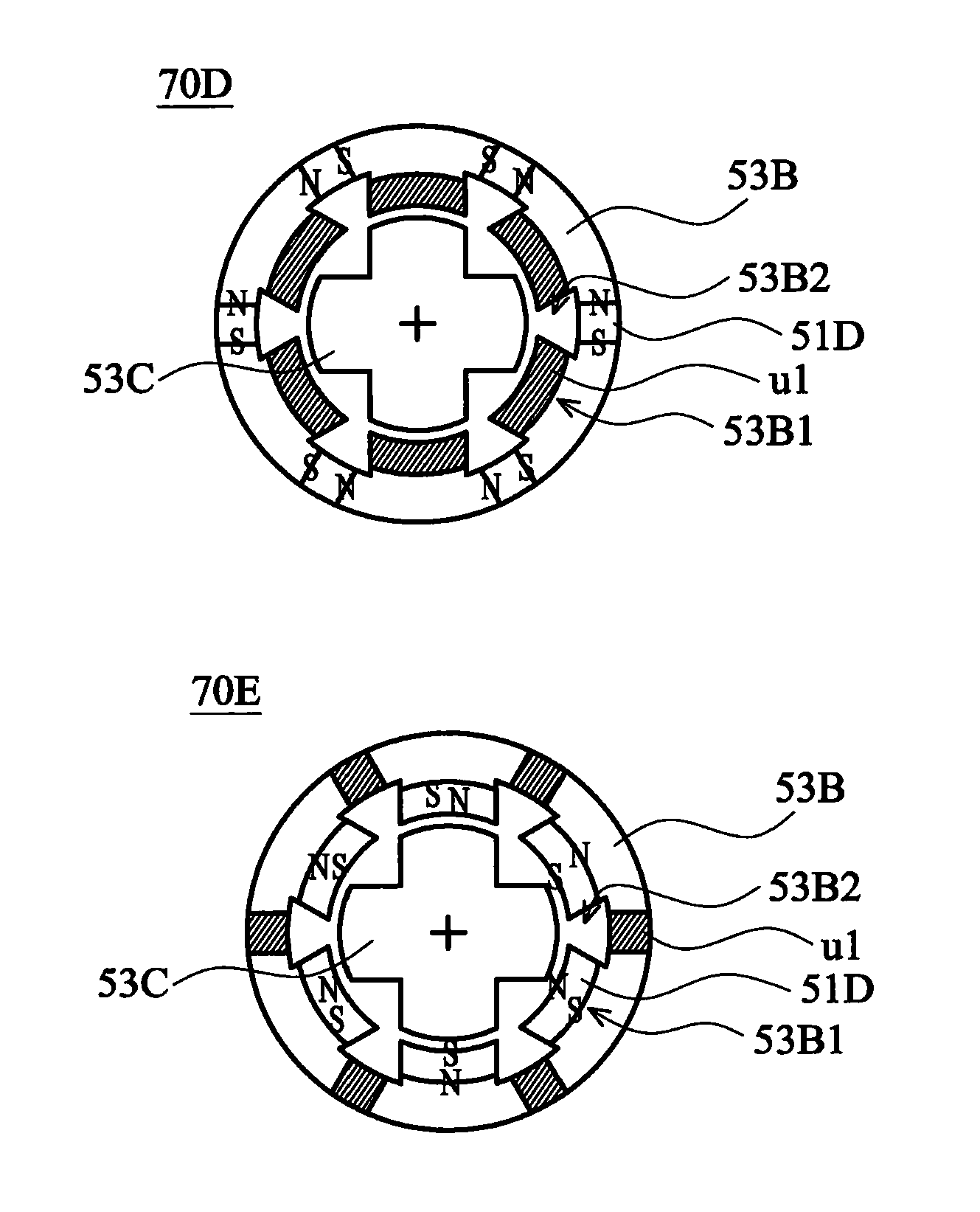
[0060]FIGS. 5A, 5B and 5C show rotating steps illustrated by cross-sectional views of a rotating magnet heat-power conversion magnetism device 50 according to an embodiment of the present invention. The rotating magnet heat-power conversion magnetism device 50 includes a magnet 51 having an axis 52 and disposed in a sleeve 53. The magnet 51 having two magnetic poles can rotate along the axis 52. The sleeve 53 is made of a high permeability magnetic material. Three magneto caloric effect material (MCEM) units u1, u2, and u3 are located at the inner face of the sleeve 53, i.e., the plurality of the MCEM units u1-u3 are arranged between the magnet 51 and the sleeve 53.

[00...


PUM


Abstract

The invention discloses a heat-power conversion magnetism device. The heat-power conversion magnetism device includes a magneto caloric effect material so that the magnetic field thereof can be changed according to the temperature difference. The heat-power conversion magnetism device rotates by changing the magnetic field of the magneto caloric effect material.

Description

CROSS REFERENCE TO RELATED APPLICATIONS[0001]The present application claims the benefit of U.S. provisional application entitled “HEAT-POWER CONVERSION MAGNETISM DEVICE”, Ser. No. 61 / 243,369, filed Sep. 17, 2009.BACKGROUND OF THE INVENTION[0002]1. Field of the Invention[0003]The invention pertains to the field of a conversion magnetism device. More particularly, the invention pertains to a heat-power conversion magnetism device.[0004]2. Description of the Related Art[0005]Converting thermal energy into power had a long period of time in human history. Especially the converting thermal energy into electrical power is the most common energy source today. However, the efficiency of conversion is still very low. For example, the efficiency is about 40% for steam power plant and about 30% for internal combustion engine. Almost 60-70% of energy is wasted. After power conversion, the remained energy becomes too low so that the temperature thereof is usually below 200° C. and mostly below 1...

Claims


Application Information

Patent Timeline
Patent Type & Authority Patents(United States)
IPC IPC(8): F25B21/00H02N10/00
CPCF25B2321/002H02N11/002H10N15/20
Inventor CHANG, SHAO HSIUNGCHANG, CHII-HOW
Owner DELTA ELECTRONICS INC
Learn More