
Alloys for hardbanding weld overlays

a technology of overlays and alloys, applied in the field of metalurgy, can solve the problems of insufficient quantifiable components, inability to include specific quantifiable components, and inability to accurately predict the production of metallic glasses

Inactive Publication Date: 2014-02-11
SULZER METCO (US) INC
View PDF8 Cites 21 Cited by
  • Summary
  • Abstract
  • Description
  • Claims
  • Application Information

AI Technical Summary

Benefits of technology

The present patent describes a weld overlay material that can be used to protect tool joints in oil and gas drilling operations and for other hardfacing applications. The material is an iron-based alloy with a fine-grained ferritic matrix that has been designed to form a crack-free hardbanding weld overlay. The alloy has a 60+ Rockwell C surface and contains carbide precipitates. The method of designing the alloy involves determining the amorphous forming epicenter composition and then creating a variant composition with predetermined changes in constituent elements. The resulting alloy is analyzed for its effectiveness and quality. Overall, the patent presents a unique solution for creating a hardbanding weld overlay that is durable and free from cracks and other defects.

Problems solved by technology

The formation of metallic glasses is very complex as compared to conventional crystalline materials, and thus modeling efforts designed to understand and predict production of metallic glasses are not very accurate.
These models typically fail to include specific quantifiable components and therefore fail to provide concrete metallic glass formation ranges.
Most materials, even those capable of forming completely amorphous structures under thermal spray processing, do not have slow enough crystallization kinetics to form an amorphous material when welded.
Most hardfacing materials, especially when dealing with weld overlays capable of exceeding 60 Rockwell C hardness, suffer from cracking during the weld process as well as poor toughness.
In addition to other problems, this cracking limits such a materials use in any application where impact occurs.
In many applications this technique offers a very good hardfacing layer, however it is difficult to apply a hardfacing layer of this type using a hard material as the matrix for the WC particles, particularly when cracking in the hardfacing layer is not desirable.
Extreme wear applications often demand improved wear performance beyond that which can be offered using a ductile matrix with WC particles, because the matrix itself is likely to wear away at an accelerated rate leaving the hard particles exposed to shatter or pull out from the surface.

Method used


Image

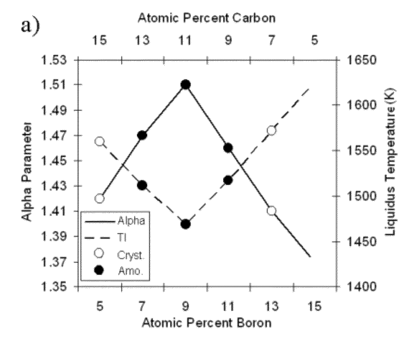
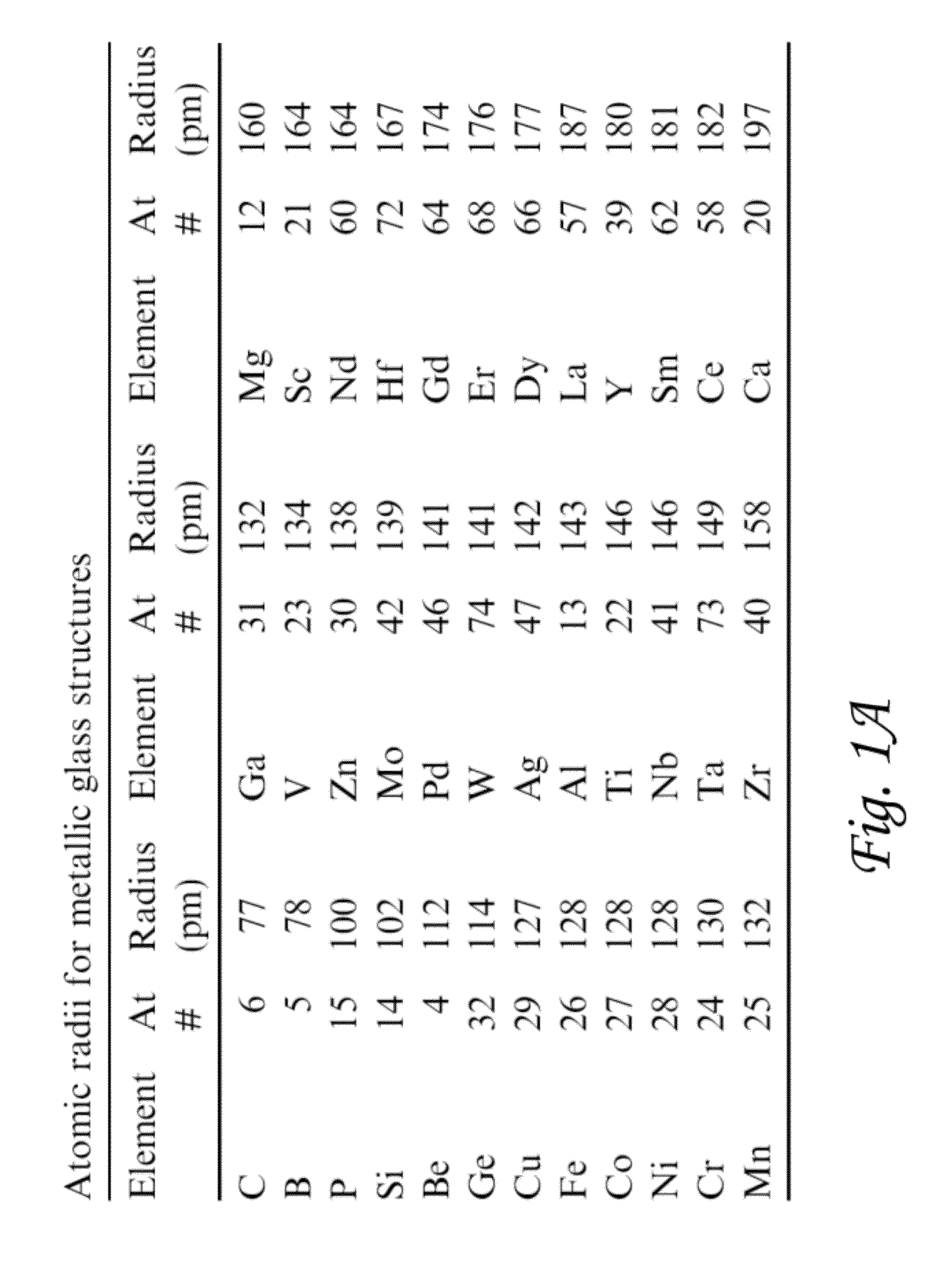
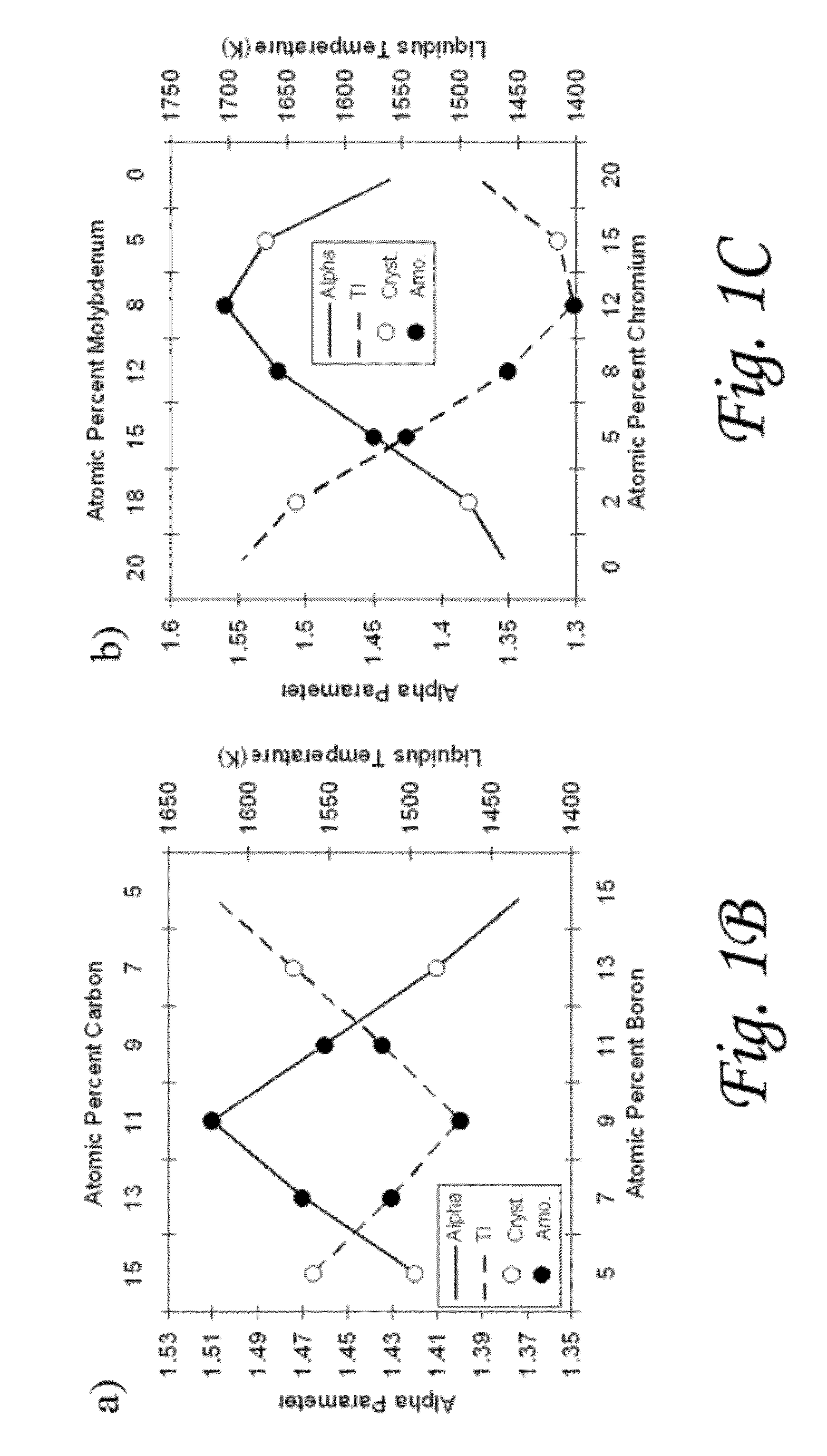
  • Alloys for hardbanding weld overlays
  • Alloys for hardbanding weld overlays
  • Alloys for hardbanding weld overlays

Examples


Embodiment Construction

[0010]According to certain aspects of the present disclosure, weld overlay materials are disclosed. In some embodiments, one or more materials of the present disclosure can be used as a superior weld overlay material for the protection of tool joints in oil and gas drilling operations. In some embodiments, one or more materials of the present disclosure can be used for other overlay hardfacing applications.

[0011]According to certain aspects of the present disclosure, an iron-based alloy is provided. The alloy can have a microstructure comprising a fine-grained ferritic matrix. The alloy can have a 60+ Rockwell C surface. The ferritic matrix can comprise <10 μm Nb and W carbide precipitates.

[0012]According to certain aspects of the present disclosure, a method of welding is provided. The method can comprise forming a crack free hardbanding weld overlay coating with an iron-based alloy. The alloy can have a microstructure comprising a fine-grained ferritic matrix. The alloy can have a...


PUM

PropertyMeasurementUnit
sizesaaaaaaaaaa
grain sizesaaaaaaaaaa
grain sizeaaaaaaaaaa

Abstract

Disclosed herein are iron-based alloys having a microstructure comprising a fine-grained ferritic matrix and having a 60+ Rockwell C surface, wherein the ferritic matrix comprises <10 μm carbide precipitates. Also disclosed are methods of welding comprising forming a crack free hardbanding weld overlay coating with such an iron-based alloy. Also disclosed are families of alloys capable of forming crack-free weld overlays after multiple welding passes.

Description

CROSS-REFERENCE TO RELATED APPLICATIONS[0001]This application is a continuation in part of and claims priority from U.S. patent application Ser. No. 12 / 939,093, filed Nov. 3, 2010, which was a continuation in part of and claims priority from U.S. patent application Ser. No. 12 / 885,276, filed Sep. 17, 2010 which was a continuation in part of and claimed priority from U.S. patent application Ser. No. 12 / 569,713, filed Sep. 29, 2009, and further claimed priority from Provisional U.S. Application Ser. No. 61 / 243,498, filed Sep. 17, 2009, and Provisional U.S. Application Ser. No. 61 / 309,354, filed Mar. 1, 2010; each of which is hereby incorporated herein by reference in its entirety for all purposes.TECHNICAL FIELD[0002]The present invention relates generally to metallurgy. More particularly, some embodiments relate to: amorphous, nanocrystalline, or microcystalline metals; and weld overlay materials.DESCRIPTION OF THE RELATED ART[0003]Amorphous metallic materials made of multiple compon...

Claims


Application Information

Patent Timeline
Patent Type & Authority Patents(United States)
IPC IPC(8): C22C38/02C22C38/32C22C38/14C22C38/12
CPCC22C38/28C22C1/1068C22C38/32B23K35/308C22C38/58C22C38/02C22C38/38C22C38/54C22C38/04C22C38/22C21D2211/004C21D2211/005B23K35/3093C22C38/24C23C4/06C23C30/00C22C38/44C22C38/46C22C38/06C22C38/48C22C38/26C22C38/34B23K35/3053C22C33/08C22C38/50C23C4/085C22C45/02C23C4/073
Inventor CHENEY, JUSTIN LEEMADOK, JOHN HAMILTON
Owner SULZER METCO (US) INC
Learn More