Supercharge Your Innovation With Domain-Expert AI Agents!

Generator with improved generation efficiency and rotational force

a technology of rotational force and generation efficiency, applied in the field of generators, can solve the problems of large rotational force for rotating magnets, large energy consumption, and relatively heavy weight, and achieve the effects of increasing the rotational force between magnet plates and coil plates, increasing generation energy, and improving generating quality

Active Publication Date: 2014-02-11
JANG SUK HO
View PDF6 Cites 0 Cited by
  • Summary
  • Abstract
  • Description
  • Claims
  • Application Information

AI Technical Summary

Benefits of technology

The generator achieves higher energy generation efficiency and rotational force even with weak power sources, maintaining efficiency under load conditions by utilizing repulsive forces and direct current conversion, thus improving economic efficiency and power production.

Problems solved by technology

However, the conventional generators as mentioned above must rotate a magnet, which is relatively heavy weight.
Because the conventional generator requires the strong enough motor power, consequently the energy consumption is very high.
Further, the attractive force acts as rotational resistance, it causes to consume the large rotational force for rotating the magnet.
In particular, the conventional cylindrical magnet and iron core cannot but adopt a tetra-polar induction method due to the constraint of installation space.
Accordingly, the high-speed rotation is needed to produce electricity of necessary capacity and due to that; it has a problem that economic efficiency is considerably low.
Because of this, a considerable quantity of electric energy is lost at the drive motor and generator.
Therefore, it is considerably inefficient in terms of energy use and low in economic efficiency.
Therefore, it has a problem in that if wind power or water power is weak, sufficient generation capacity cannot be obtained and the generation efficiency is low.

Method used


Image

  • Generator with improved generation efficiency and rotational force
  • Generator with improved generation efficiency and rotational force
  • Generator with improved generation efficiency and rotational force

Examples


Embodiment Construction

[0021]Terms or words used in the specification and claims should not be construed as limited to a lexical meaning, and should be understood as appropriate notions by the inventor based on that he / she is able to define terms to describe his / her invention in the best way to be seen by others. Therefore, embodiments and drawings described herein are simply exemplary and not exhaustive, and it will be understood that various modifications and equivalents may be made to take the place of the embodiments.

[0022]Hereinafter, preferred embodiments of the present invention will be described in more detail with reference to the accompanying drawings.

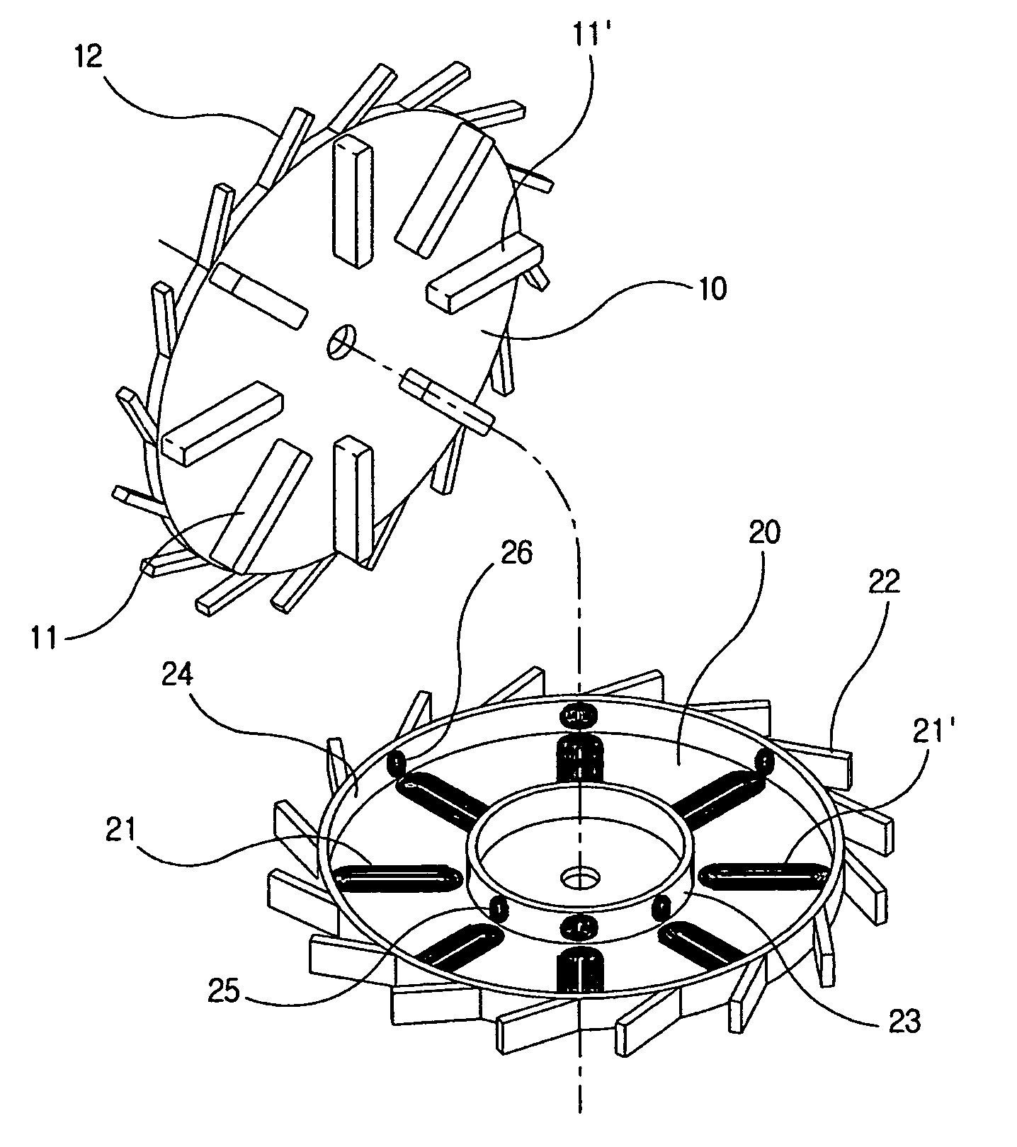
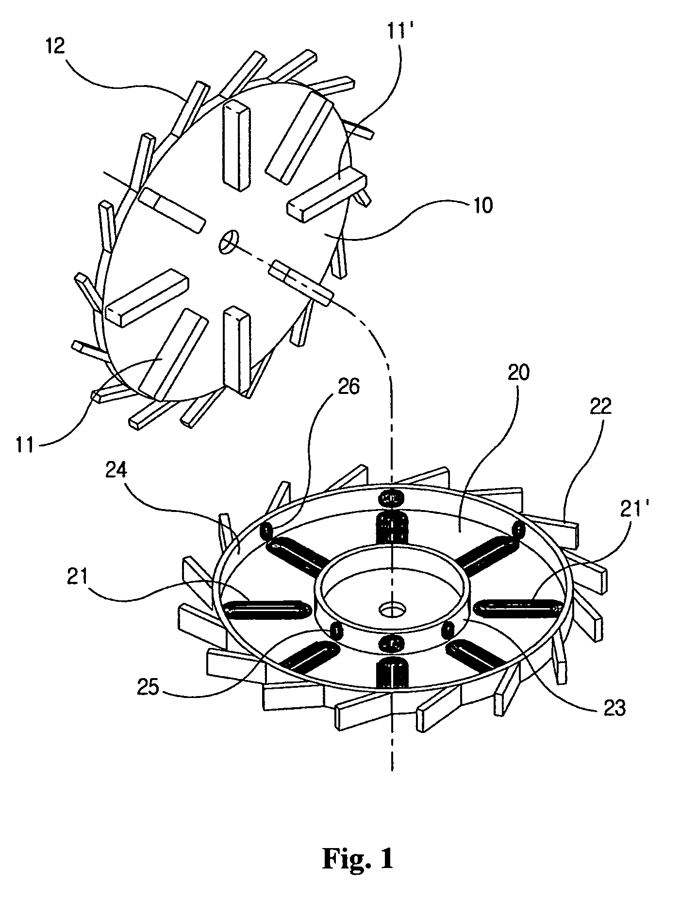
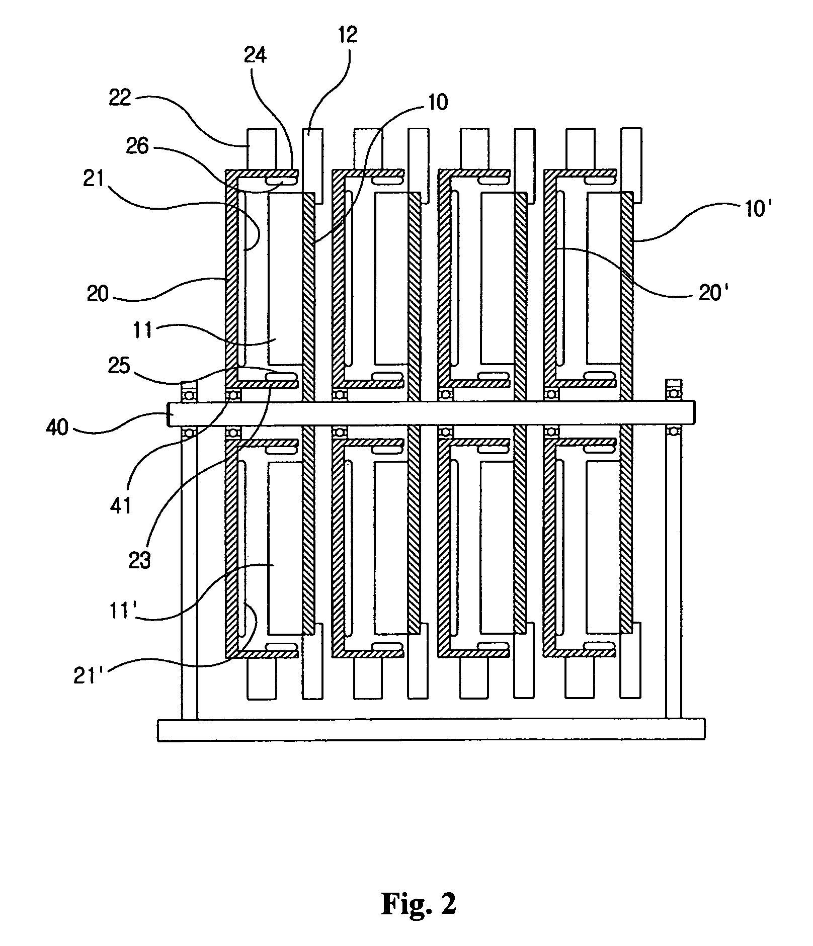
[0023]FIG. 1 is an exploded perspective view showing a magnet plate and coil plate of a generator according to the present invention, FIG. 2 is a sectional view showing the assembled state of the generator according to the present invention, and FIG. 3 is an enlarged sectional view showing major parts of the generator according to the present inven...


PUM


Abstract

An improved generator for using waterpower, wave-power or wind-power, comprising; a set of magnet plates and coil plates for mounting on a rotating shaft in parallel, the magnets installed on the magnet plates and the generating coils installed on the coil plates with constant-intervals in radial direction, a plurality of blades obliquely installed on circumference of the magnet plates and coil plates with mutually opposite direction, an inner annular cylinder and outer annular cylinder mounted on the coil plates to form annular container for inserting the magnets. A plurality of induction coils installed on the inner annular cylinder, a plurality of electromotive coils installed on the outer annular cylinder for proximately contact with ends of the magnets. The magnet plates and coil plates rotate in mutually opposite direction to enhance the quality of generation and repulsive force. Thus, the rotational reaction force is continuously generated between the magnets and coil plates to enhance the rotational force.

Description

BACKGROUND OF THE INVENTION[0001]1. Field of the Invention[0002]The present invention relates to a generator, which generate the electric power for using waterpower, wave-power or wind-power. More particularly, the improved generator has multi coil plates mounting the generating coils with constant intervals in radial direction, and the magnet plates mounting a plurality of magnets with constant intervals in radial direction that are installed on a rotating shaft in parallel. A plurality of induction coils and electromotive coils installed on inner and outer annular cylinders proximately contacting the opposite end of the magnets. Thus, the improved generator increase the efficiency as the coil plates and magnet plates are rotating in mutually opposite direction, as well as the rotational force is enhanced by increasing the repulsive force between coil plates and magnet plates.[0003]2. Related Prior Art[0004]A generator is a device, which converts the dynamic energy to the electric ...

Claims


Application Information

Patent Timeline
Patent Type & Authority Patents(United States)
IPC IPC(8): H02K9/00H02K1/22H02K21/12
CPCF05B2210/16Y02E10/74Y02E10/223H02K2213/12H02K21/24H02K7/1823H02K16/00F05B2240/941F03B3/00F03D3/00Y02E10/20H02K17/42
Inventor JANG, SUK, HO
Owner JANG SUK HO
Features
  • R&D
  • Intellectual Property
  • Life Sciences
  • Materials
  • Tech Scout
  • Unparalleled Data Quality
  • Higher Quality Content
  • 60% Fewer Hallucinations
Learn More