Induction system with air flow rotation and noise absorber for turbocharger applications

a technology of air induction system and turbocharger, which is applied in the direction of combustion air/fuel air treatment, wind motor with parallel air flow, perpendicular air flow, etc. it can solve the problems of turbocharger noise during its operation, air induction system is prone to being ever more restrictive, and turbocharger requires power to operate, etc., to minimize the noise escape of the turbocharger, the effect of facilitating the functionality of the turbine wheel

Inactive Publication Date: 2014-02-18
GM GLOBAL TECH OPERATIONS LLC
View PDF36 Cites 32 Cited by
  • Summary
  • Abstract
  • Description
  • Claims
  • Application Information

AI Technical Summary

Benefits of technology

[0005]The present invention is an improved air induction system for a turbocharger which minimizes pressure losses, assists the functionality of the turbine wheel, and minimizes escape of turbocharger noise.
[0010]The acquired air flow rotation provided by the air induction system according to the present invention has a number of advantages. Because the acquired air flow rotation is in the same rotational direction as the turbine wheel rotation, the dynamic pressure load on the compressor blades is reduced. This pressure load reduction increases turbocharger efficiency and more than compensates for the pressure loss of the air intake housing. As a consequence, the turbine wheel generates less heat, vibration and noise, with the added benefit of improved durability. An additional advantage involves the synergism of the helical vane with respect to the perforated tube, in that the acquired rotation of the air flow encourages sound waves to deflect their propagation direction so as to pass radially through the perforations and into the acoustic cavity, thereby reducing noise from the turbocharger exiting the air entry port of the air induction housing. In addition, the spiral vane reflects acoustic energy back into the turbocharger due to a change in acoustic impedance. Therefore, the combination of the helical vane and the perforated tube serves to rotate the air flow, deflect sound waves into the perforations and reflect sound waves (i.e., acoustic energy) back to turbocharger.
[0011]Accordingly, it is an object of the present invention to provide a turbocharger air induction housing which minimizes pressure losses, assists the functionality of the turbine wheel, and minimizes escape of turbocharger noise.

Problems solved by technology

Problematically, the turbocharger requires power to operate, inclusive not only of the power needed to rotate the turbine wheel but also to overcome pressure losses in the air induction housing.
Problematically further, the turbocharger produces noise during its operation which can undesirably exit at the air entry port of the air induction housing.
Minimization of pressure loss at the air intake housing and lowering of turbocharger noise exiting therefrom are a challenge, particularly in view of increasing demands for improved engine performance, turbocharger drivability, fuel economy, and emissions reduction.
As a result of these integrated components, air induction systems are prone to being ever more air flow restrictive.

Method used


Image

  • Induction system with air flow rotation and noise absorber for turbocharger applications
  • Induction system with air flow rotation and noise absorber for turbocharger applications
  • Induction system with air flow rotation and noise absorber for turbocharger applications

Examples


Embodiment Construction

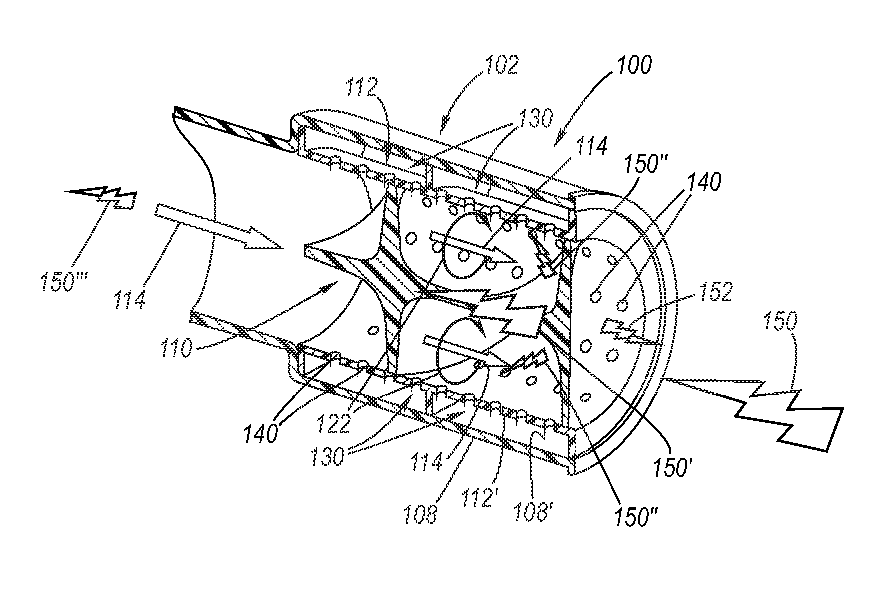
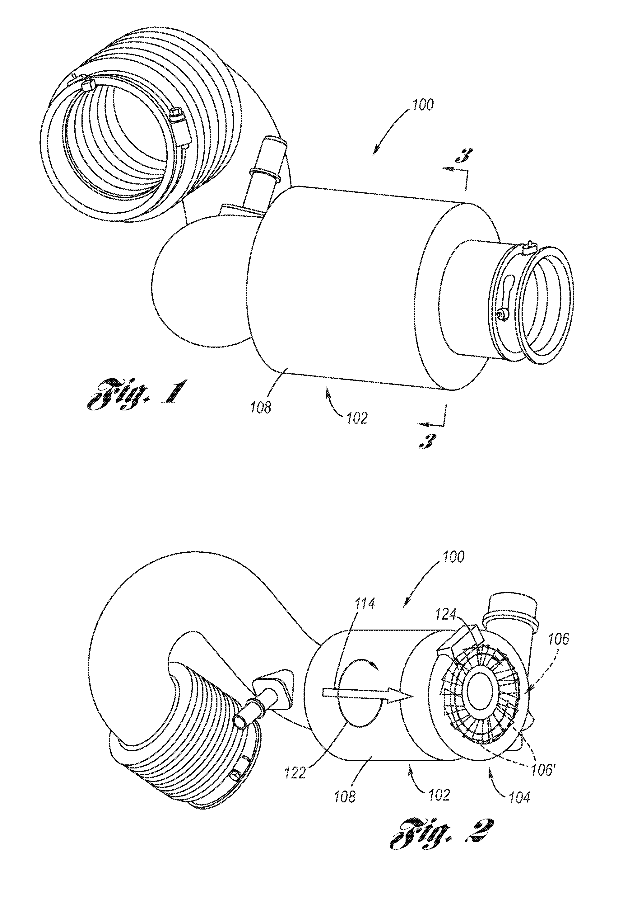
[0023]Referring now to the Drawings, FIGS. 1 through 10 depict examples of an improved air induction system for a turbocharger which minimizes pressure losses, assists the functionality of the turbine wheel, and minimizes escape of turbocharger noise.

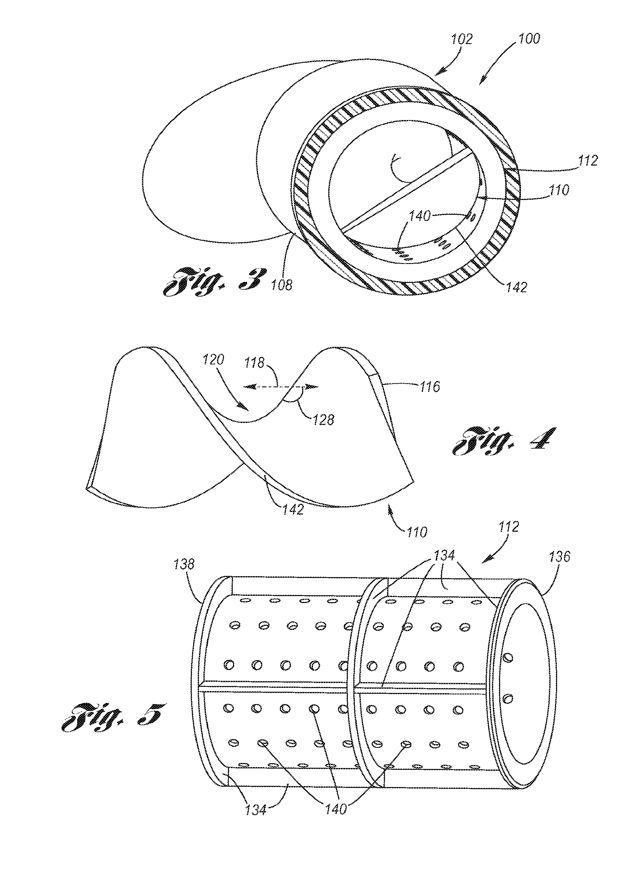
[0024]FIGS. 1 through 3 depict an example of an improved air induction system 100, showing an exemplar air induction housing 102 thereof, which may have other configurations (see for example the discussion hereinbelow of FIG. 10). The air induction housing 102 is connected to a turbocharger 104. Internal to the turbocharger 104 is a turbine wheel 106 having blades 106′ which rotate in a predetermined direction of rotation 124 so as to draw air from the upstream disposed air induction housing 102 and deliver the air, now under compression, to a downstream engine intake manifold (not shown).

[0025]The air induction housing 102 includes a cylindrical main flow tube 108. Disposed within the main flow tube 108 is a helical vane 110, and, pref...


PUM


Abstract

An air induction system consisting of a cylindrical main flow tube, a helical vane disposed within the main flow tube, and, preferably, a noise absorbing perforated tube disposed within the main flow tube in concentric relation to the helical vane. The twist direction of the helical vane provides air flow rotation in the same direction of rotation as the turbine wheel. The helical vane causes noise reflection and enhancement of noise attenuation by the perorated tube and its adjoining one or more acoustic cavities.

Description

TECHNICAL FIELD[0001]The present invention relates to air induction systems for turbochargers, and more particularly to an air induction system which imparts air flow rotation upstream of, and rotationally in the same direction as, the turbocharger turbine wheel, and which, further, attenuates turbocharger noise.BACKGROUND OF THE INVENTION[0002]Turbochargers for internal combustion engines utilize a rotating turbine wheel to draw air from an upstream air induction housing and deliver the air, now under compression, to a downstream engine intake manifold. Problematically, the turbocharger requires power to operate, inclusive not only of the power needed to rotate the turbine wheel but also to overcome pressure losses in the air induction housing. Problematically further, the turbocharger produces noise during its operation which can undesirably exit at the air entry port of the air induction housing.[0003]When an air induction system for a turbocharger is designed, taken into account...

Claims


Application Information

Patent Timeline
Patent Type & Authority Patents(United States)
IPC IPC(8): F04D29/44
CPCF02M35/1227F02M35/10157F02M35/1211F02B37/00F02M35/1216Y02T10/144Y02T10/12
Inventor LI, LEI
Owner GM GLOBAL TECH OPERATIONS LLC
Why Eureka
Try Eureka