Liquid-crystal apparatus, method for manufacturing the same, and electronic device

a technology of liquid crystal apparatus and liquid crystal, which is applied in the direction of instruments, non-linear optics, optics, etc., can solve the problems of unfavorable productivity, method is expensive, and machine costs are usually high

Active Publication Date: 2014-02-18
SEIKO EPSON CORP
View PDF7 Cites 2 Cited by
  • Summary
  • Abstract
  • Description
  • Claims
  • Application Information

AI Technical Summary

Benefits of technology

[0007]Advantages of some aspects of the invention are to provide a liquid-crystal apparatus that has a flat layer on depressions and can be produced with no need for spending long periods of time for the formation and grinding of the coating covering the depressions, to provide a method for manufacturing such a liquid-crystal apparatus, and to provide an electronic device equipped with such a liquid-crystal apparatus.
[0010]In these aspects of the invention, any depressions are plugged up with the insulating coating formed thereon; the uppermost layer of the element substrate is flat. The insulating coating has poor step coverage, and the use of this insulating coating allows relatively large depressions to be formed in the preexisting depressions. As the coating process proceeds, the wall of each new depression, made from the insulating coating, becomes thicker and finally closes at the top to contain a void therein. As mentioned above, the insulating coating is then ground to some extent, but the voids are kept closed; the insulating coating can have a flat surface despite the presence of the voids. This means that the insulating coating may be thinner than in the case where the depressions are completely plugged up and that the coating process can be finished faster accordingly. Furthermore, less amount of material is needed to form the insulating coating, making the coating process friendly to the environment. Moreover, the grinding process can also be finished relatively fast owing to the small thickness of the insulating coating. These are the reasons why some aspects of the invention make it possible to produce a flat layer on depressions with no need for spending long periods of time for the formation and grinding of the coating covering the depressions. The small thickness of the insulating coating leads to a small amount of the insulating coating to be ground. This offers another advantage, a reduced thickness variability of the ground insulating coating. This accordingly improves the uniformity of the liquid-crystal cell gap and that of the effective voltage applied to the liquid crystals, thereby giving the liquid-crystal apparatus an improved display performance. Furthermore, using an insulating coating to seal the depressions is advantageous in that the coater and the grinder for interlayer or other insulating coatings can be directly used; no additional machines are needed.
[0012]Preferably, the voids are contained in the depressions at least in part. The use of an insulating coating of poor step coverage allows the depressions to be closed near the rim thereof, and thus the voids are contained in the depressions at least in part. This way of forming the closed voids allows the voids to be closed relatively fast, thereby reducing the time before the coating process can be finished. As a result, the grinding process can also be finished relatively fast. The rapid completion of the coating and grinding of the insulating coating leads to an improved productivity. Furthermore, the thickness variability of the ground insulating coating is reduced.
[0015]It may be also allowed that an oriented coating is formed to cover the insulating coating. This constitution provides the oriented coating with a flat surface, hence easier and more precise control of the orientation of the liquid crystals.

Problems solved by technology

Unfortunately, the constitutions described in this publication are unfavorable in terms of productivity because it takes a long time to form the metal coating and grind it and for other reasons.
To make matters worse, this method is costly; it involves the use of a coater that can produce a metal coating of good step coverage and the use of a grinder for metal surfaces, and such machines are usually expensive.
The insulating coating has poor step coverage, and the use of this insulating coating allows relatively large depressions to be formed in the preexisting depressions.
Moreover, the grinding process can also be finished relatively fast owing to the small thickness of the insulating coating.

Method used


Image

  • Liquid-crystal apparatus, method for manufacturing the same, and electronic device
  • Liquid-crystal apparatus, method for manufacturing the same, and electronic device
  • Liquid-crystal apparatus, method for manufacturing the same, and electronic device

Examples


embodiment 1

Overall Constitution

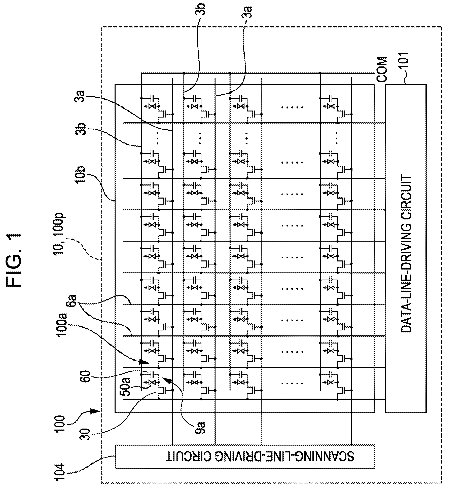
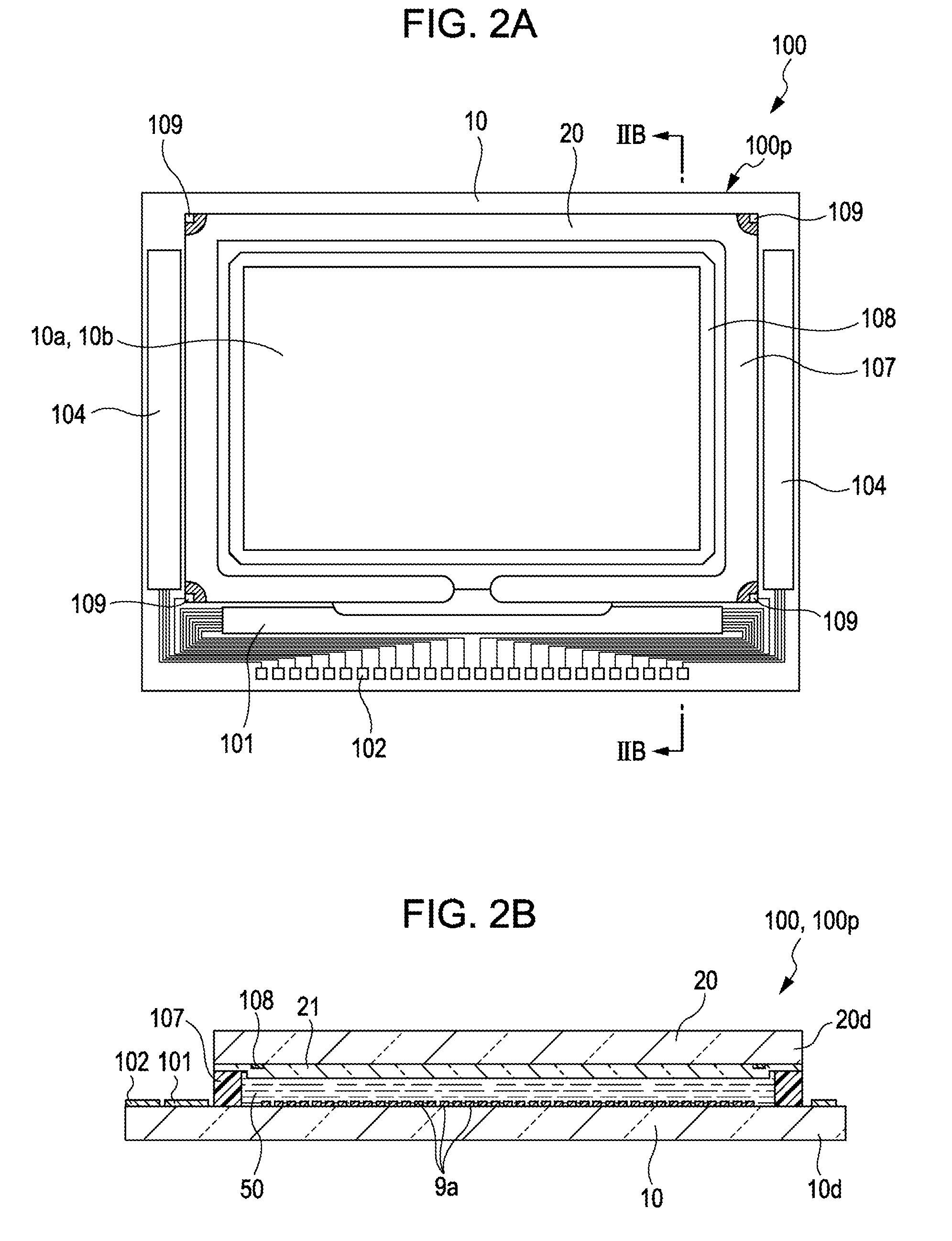
[0028]FIG. 1, a block diagram, illustrates the electrical wiring of a liquid-crystal apparatus according to Embodiment 1, and FIGS. 2A and 2B illustrate the same liquid-crystal apparatus in more detail. More specifically, FIG. 2A is a plan view of the liquid-crystal panel and related components of the liquid-crystal apparatus seen from the opposite substrate side, and FIG. 2B a cross-sectional view of FIG. 2A taken along line IIB-IIB.

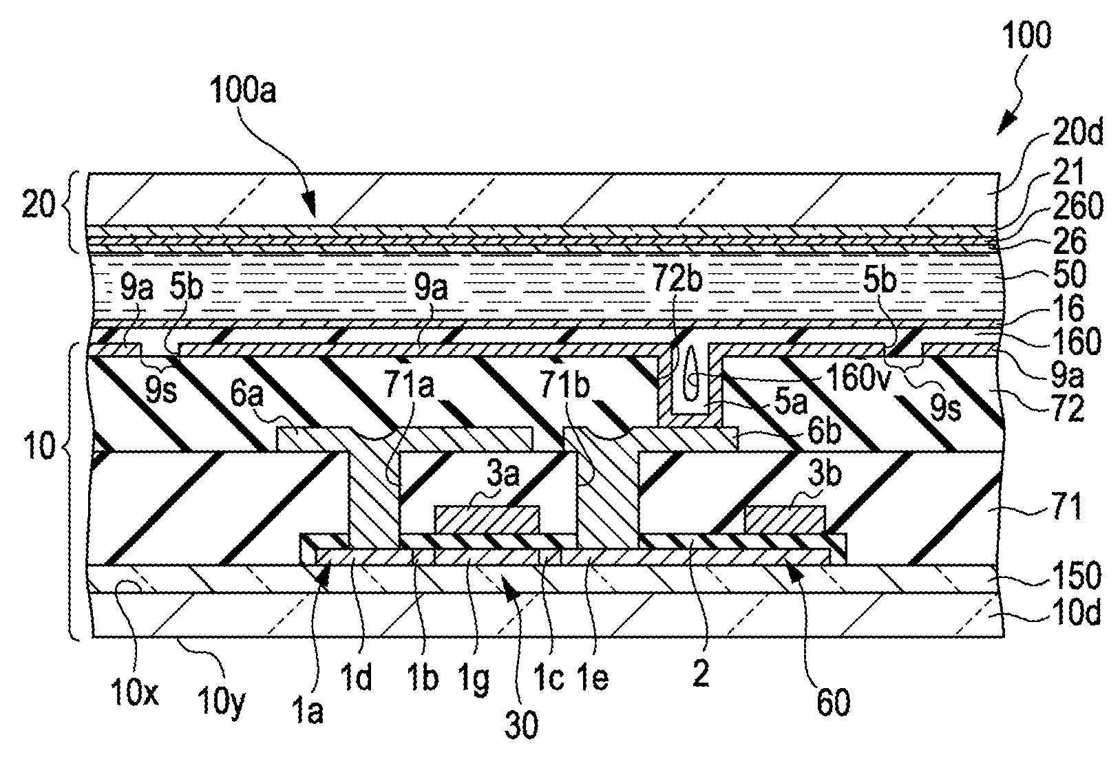
[0029]As illustrated in FIG. 1, this liquid-crystal apparatus 100 has a reflective liquid-crystal panel 100p. This liquid-crystal panel 100p has a pixel field 10b. On the central portion of this pixel field 10b, several pixels 100a are arranged in a matrix. The liquid-crystal panel 100p is based on an element substrate 10 (will be detailed later), and this element substrate 10 has several data lines 6a and several scanning lines 3a extending thereon within the pixel field 10b and crossing each other at right angles; each point of int...

embodiment 2

[0064]FIGS. 6A to 6C illustrate a liquid-crystal apparatus 100 according to Embodiment 2. More specifically, FIG. 6A is a plan view of an adjacent pair of pixels on the element substrate 10 of this liquid-crystal apparatus 100, FIG. 6B a cross-sectional view of FIG. 6A taken along ling VIB-VIB, and FIG. 6C an enlarged cross-sectional diagram illustrating a depression 5a, another depression 5b, and surroundings. Embodiment 2 has basically the same constitution as Embodiment 1; the components common for both embodiments are referenced by like numbers in the drawings involved and are not detailed here.

[0065]As illustrated in FIGS. 6A to 6C, the element substrate 10 of a liquid-crystal apparatus 100 according to this embodiment has a constitution similar to that of the one described in Embodiment 1 as follows. The element substrate 10 has an insulating coating 72, and this insulating coating 72 is a silicon dioxide coating formed by CVD. The interlayer insulating coating 72 has a flat s...


PUM

PropertyMeasurementUnit
aspect ratioaaaaaaaaaa
diameteraaaaaaaaaa

Abstract

A liquid-crystal apparatus has an element substrate. This element substrate contains depressions inside, and these depressions are sealed with an insulating film, a silicon dioxide coating. To this end, the insulating film is formed by chemical vapor deposition, and this coating process lasts until voids formed in the depressions are closed at the top by the insulating film. Then, the insulating coating is ground. This grinding process lasts until the insulating film is flat, but should be terminated before the voids are opened.

Description

[0001]Japanese Patent Application No. 2010-025178, filed Feb. 8, 2010 is incorporated by reference in its entirety herein.BACKGROUND[0002]1. Technical Field[0003]The present invention relates to a liquid-crystal apparatus, a method for manufacturing the liquid-crystal apparatus, and an electronic device equipped with the liquid-crystal apparatus.[0004]2. Related Art[0005]Liquid-crystal apparatuses have an element substrate and another substrate facing it, namely, an opposite substrate. The element substrate has pixel electrodes formed thereon, and the opposite substrate and the element substrate sandwich a liquid-crystal layer therebetween. The element substrate has some more elements and layers placed thereon; for example, pixel transistors, pixel electrodes, an insulating coating, and an oriented coating are layered in this order. Preferably, the uppermost layer of the element substrate is flat. Some measures can be taken to achieve this. A possible solution is to seal depressions...

Claims


Application Information

Patent Timeline
Patent Type & Authority Patents(United States)
IPC IPC(8): G02F1/136G02F1/1333
CPCG02F1/1343G02F1/136227
Inventor JIROKU, HIROAKI
Owner SEIKO EPSON CORP
Why Eureka
Try Eureka