Condensation dryer with a housing

a dryer and housing technology, applied in the direction of cleaning using liquids, lighting and heating apparatus, container discharge methods, etc., can solve the problems of loss of energy and energy in the drying process, and achieve the effect of reducing pressure loss and optimizing flow

Inactive Publication Date: 2014-02-25
BSH BOSCH & SIEMENS HAUSGERAETE GMBH
View PDF31 Cites 22 Cited by
  • Summary
  • Abstract
  • Description
  • Claims
  • Application Information

AI Technical Summary

Benefits of technology

[0027]The invention is advantageous in that the process air can be routed into the drying chamber with an opt...

Problems solved by technology

This drying process is very energy-intensive, since the heat, which is extracted from the cold ai...

Method used


Image

  • Condensation dryer with a housing
  • Condensation dryer with a housing
  • Condensation dryer with a housing

Examples


Embodiment Construction

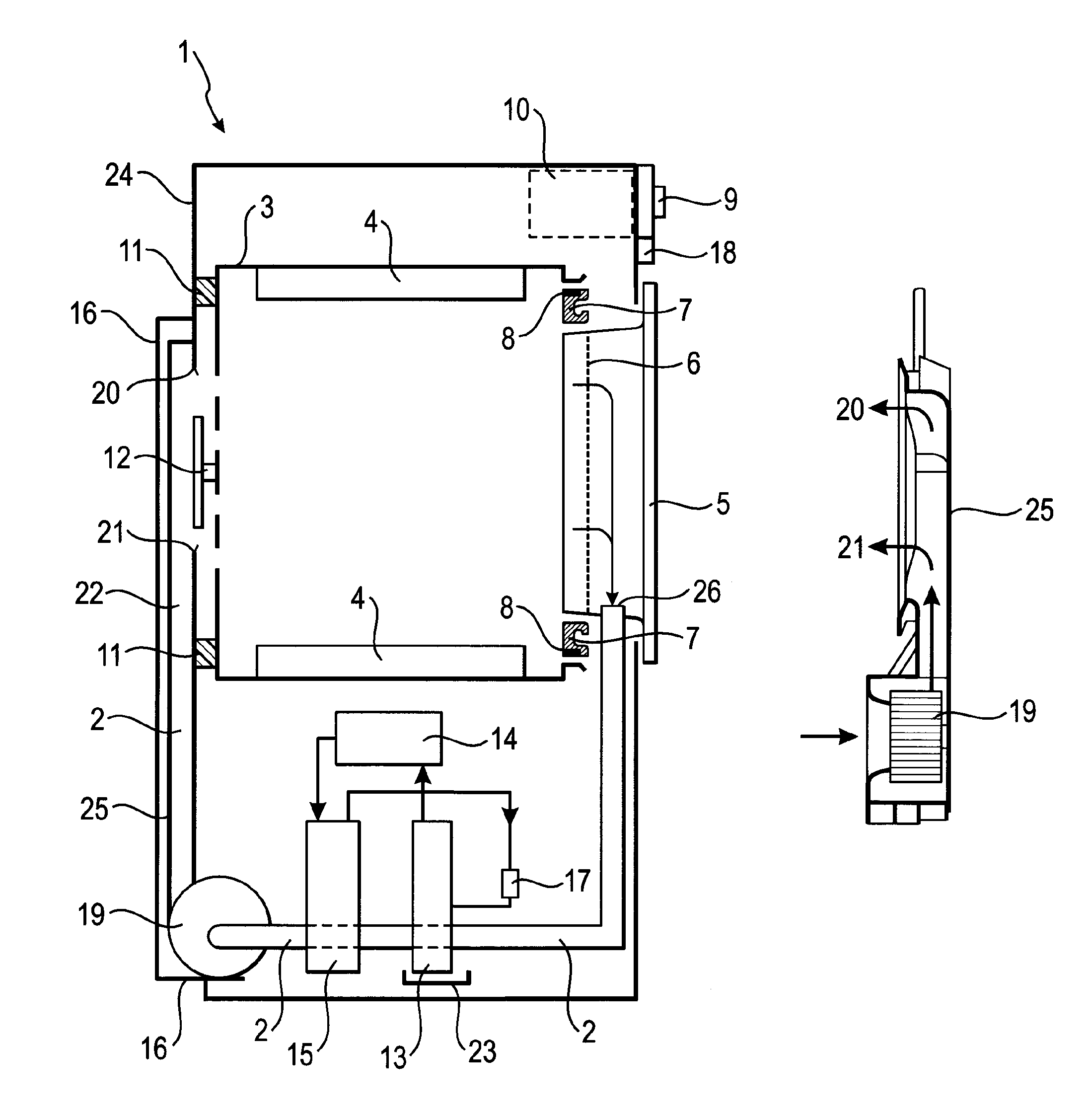
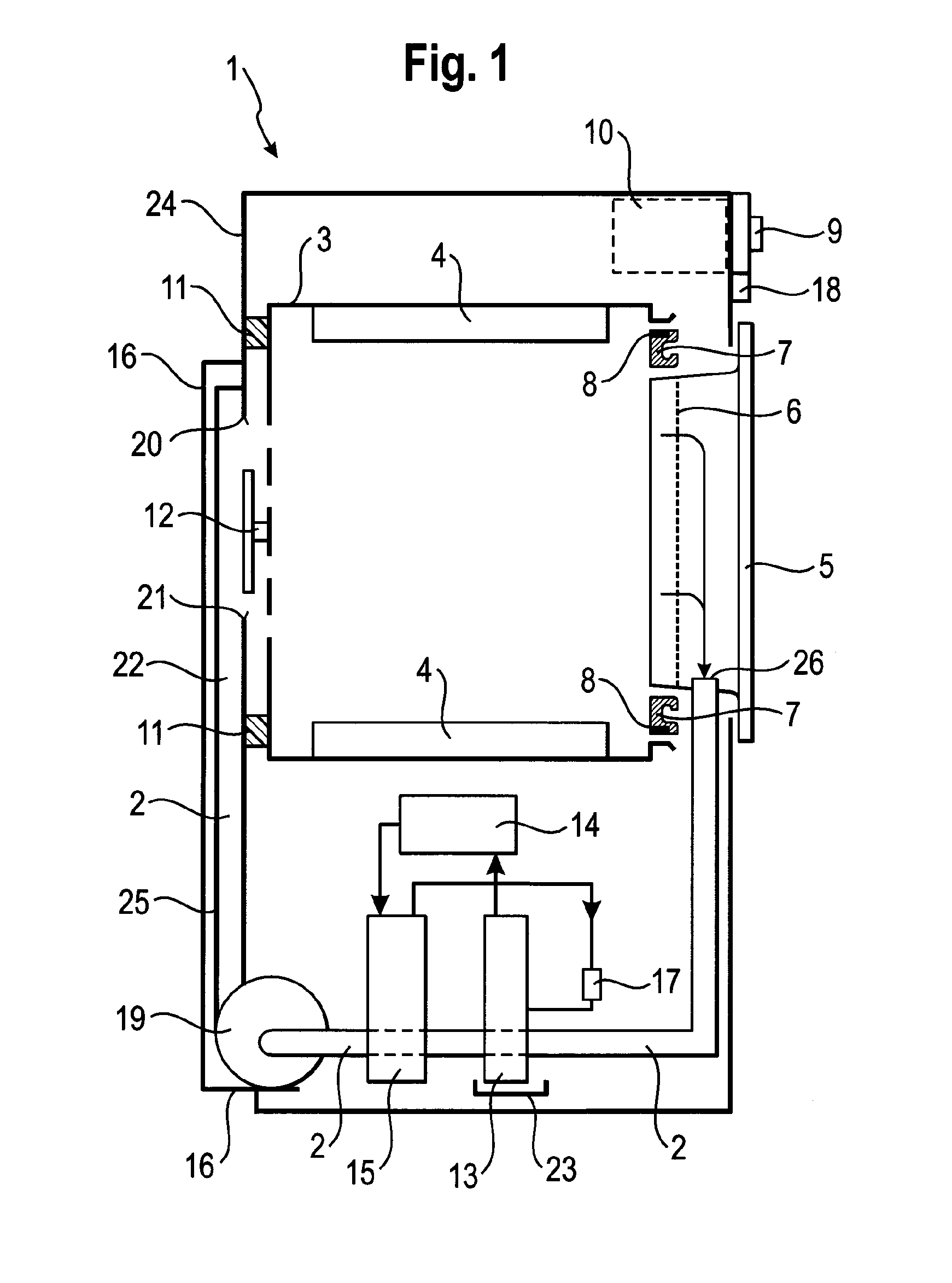
[0035]FIG. 1 shows a vertical section through a condensation dryer 1 (subsequently abbreviated to “dryer”1) according to a first embodiment, in which the heating of the process air is exclusively carried out by way of the condenser 15 of the heat pump 13, 14, 15, 17 which functions as a heat source 15.

[0036]The dryer 1 shown in FIG. 1 comprises a drum 3 which can be rotated about a horizontal axis as a drying chamber 3, within which agitators 4 are fastened to move laundry during the rotation of the drum 3. Process air is guided through a drum 3 and a heat pump 13, 14, 15, 17 in an air channel in the closed circuit by means of a fan 19 (process air circuit 2). After passing through the drum 3, the moist, warm process air is cooled down and is heated again after the moisture contained in the process air has condensed. Heated air is routed here from the rear, i.e. from the side of the drum 3 opposite a door 5, through its perforated base into the drum 3, comes into contact there with ...


PUM


Abstract

A condensation dryer includes a housing having a wall area which forms a rear side, and a process air circuit for circulating process air. The process air circuit has a first section outside the housing and running along the wall area and a remaining second section inside the housing. The first section which is located at the wall area is formed by a profile part placed on the wall area and is covered by a hood placed in sealing fashion on the wall area. A fan is arranged in the process air circuit for circulating the process air, and a drying chamber is arranged in the process air circuit for holding objects to be dried. A heat pump is disposed in the housing and includes a heat sink which is thermally coupled to the process air circuit, and a heat source, which is thermally coupled to the process air circuit.

Description

BACKGROUND OF THE INVENTION[0001]The invention relates to a condensation dryer with a housing, comprising a wall area forming a rear side and with a process air circuit for circulating process air, said circuit having a section outside the housing and running along the wall area and being otherwise located inside the housing, there being located in the circuit a fan for circulating the process air and a drying chamber for holding objects to be dried, wherein the section is covered by a hood that is placed in sealing fashion on the wall area.[0002]Such a condensation dryer originates from WO 2006 / 122840 A1. The tumble dryer described there has an electrical heater for the air used to dry laundry, the so-called process air and the process air is guided through a flow channel to the heater, with the flow channel being attached as a U-shaped profile on the outside to a rear side of a housing of the dryer and being covered by a hood. As a result of the flowing process air being covered t...

Claims


Application Information

Patent Timeline
IPC IPC(8): F26B11/02
CPCD06F58/206D06F58/20
Inventor EDIGER, RAINERNAWROT, THOMAS
Owner BSH BOSCH & SIEMENS HAUSGERAETE GMBH
Why Eureka
Try Eureka