Thermal generator with magnetocaloric material

a magnetocaloric material and heat generator technology, applied in the direction of machines, lighting and heating apparatus, domestic cooling apparatus, etc., can solve the problems of increasing the risk of malfunction, limiting the useful calorific output, and increasing the number of parts, so as to reduce the space requirement of the generator and the number of moving elements

Inactive Publication Date: 2014-02-25
COOLTECH APPL SAS
View PDF18 Cites 56 Cited by
  • Summary
  • Abstract
  • Description
  • Claims
  • Application Information

AI Technical Summary

Benefits of technology

[0008]The present invention aims to overcome these disadvantages by offering a heat generator in which the number of moving elements is reduced and whose configuration allows an important reduction of the space requirement of the generator.
[0011]The integration of a single means of displacement allows limiting the number of parts of the heat generator and thus reducing its production cost. Likewise, the use of a device necessary for the operation of the generator as a device allowing to actuate the means of displacement of the heat transfer fluid allows for an even further reduction of the number of parts making up the generator and, furthermore, to reduce its space requirement.

Problems solved by technology

Its limits in terms of its useful calorific output and its efficiency are also well known.
One of the difficulties in the realization of generators that use one or more magnetocaloric elements lies in the exchange of thermal energy between these magnetocaloric elements and the circuit(s) that use, consume or exchange the thermal energy with the generator, and that are connected with the latter.
This generator nevertheless has a disadvantage related to the need for two cams to drive the two sets of pistons positioned opposite each magnetocaloric element.
This leads to an increase of the number of parts making up the generator, and more specifically of the number of moving parts and thus to an increase of the risk of malfunction, to a higher risk of wear due to the permanent contact between the cam and the pistons, and to a degradation of the efficiency of the generator.
Furthermore, the high number of parts also increases the space requirement of the generator and thus limits its ability to be integrated in environments in which the available space is reduced and limited.

Method used


Image

  • Thermal generator with magnetocaloric material
  • Thermal generator with magnetocaloric material
  • Thermal generator with magnetocaloric material

Examples


first embodiment

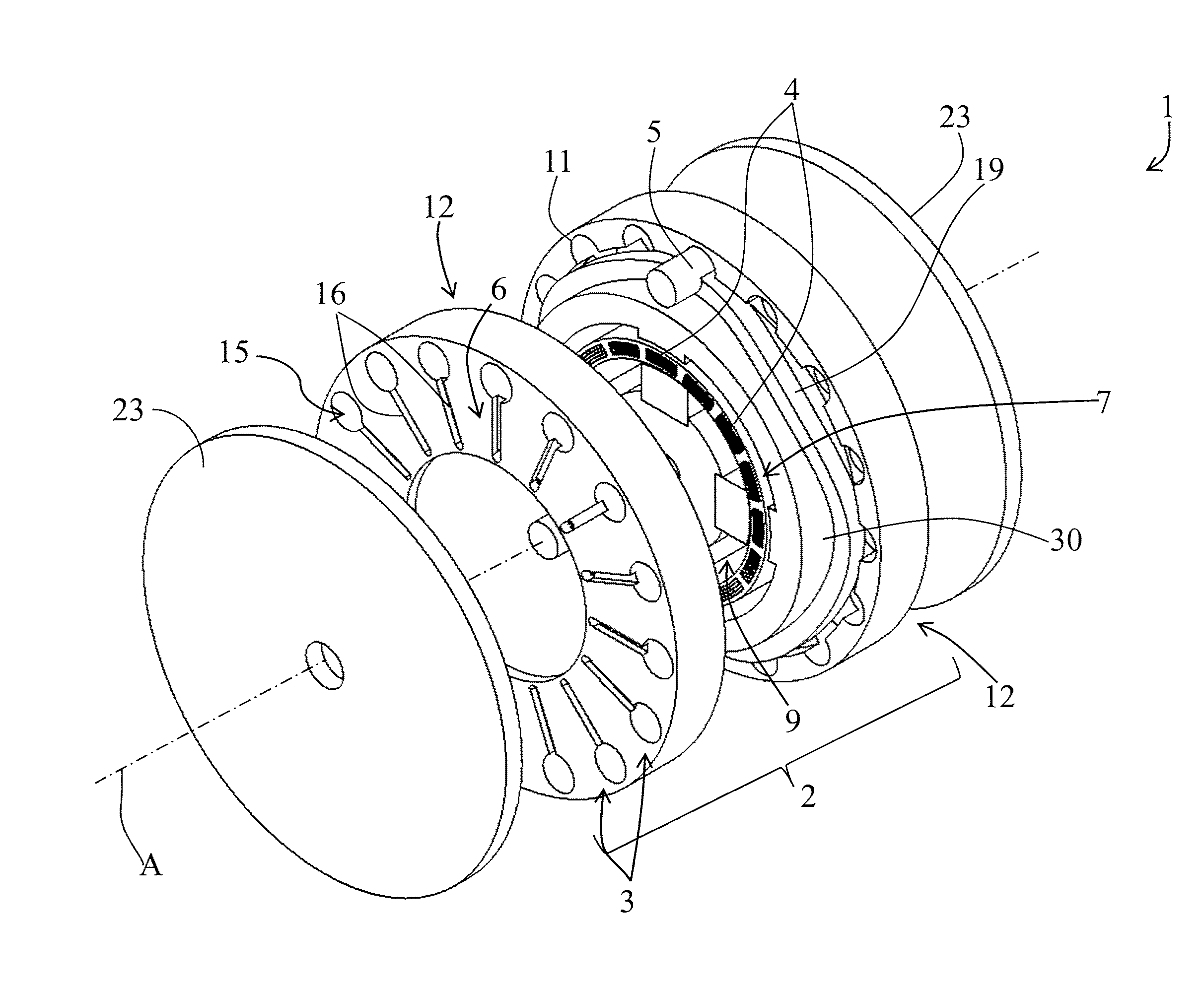
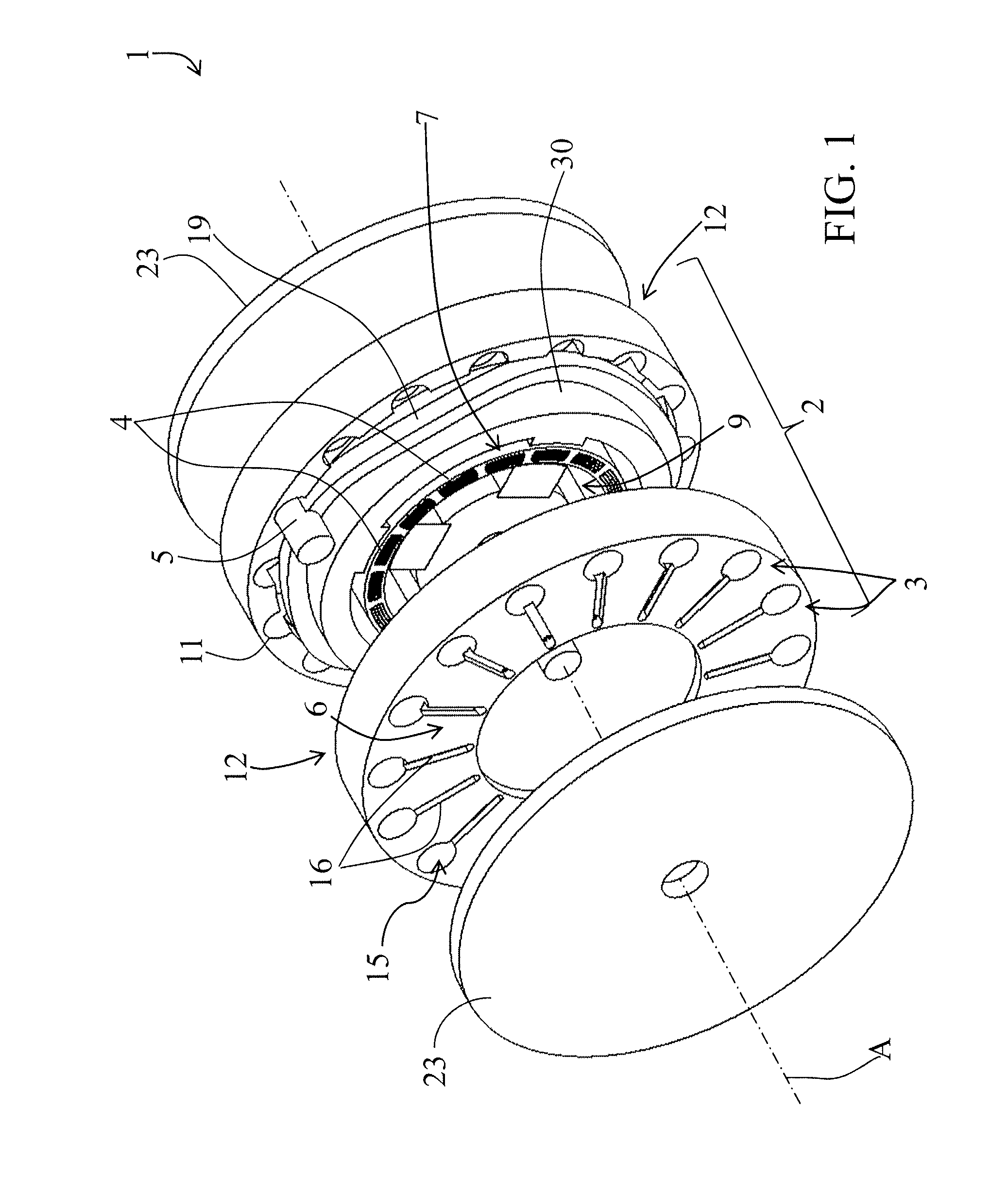
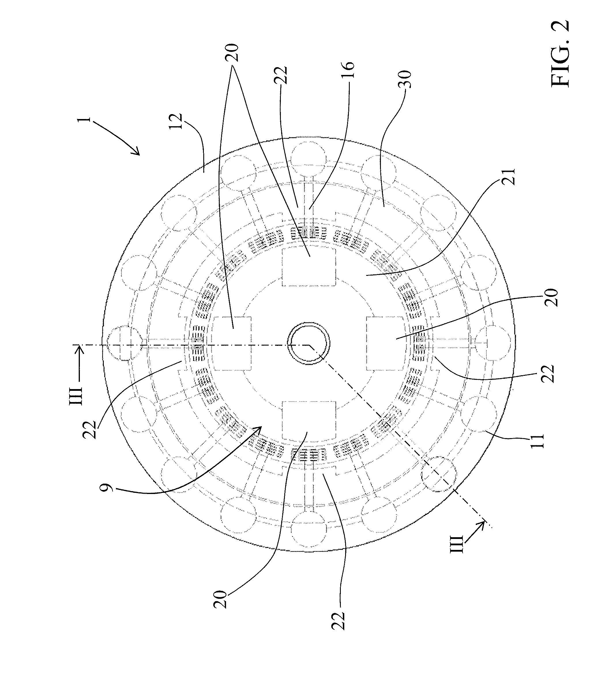
[0033]FIGS. 1 to 6 represent a heat generator 1 according to the invention, in which the structure of the generator 1 is circular.

[0034]The heat generator 1 represented in FIGS. 1 to 4 comprises only one thermal flux generating unit 2. This unit is provided with several thermal modules 3 each comprising a magnetocaloric element 4 across which a heat transfer fluid is circulated by a means of displacement 5 in the form of a piston. For simplification reasons, only one piston 5 is represented in FIG. 1. The magnetocaloric elements 4 are arranged in a circle around a central axis A and a magnetic arrangement 9 rotates around the central axis A so as to submit the magnetocaloric elements 4 to a variable magnetic field to perform alternately a heating cycle and a cooling cycle in the latter.

[0035]The magnetocaloric elements 4 are permeable to the heat transfer fluid and can be made of one or several magnetocaloric materials. They comprise open fluid passages that can be made of the pores...

second embodiment

[0047]FIGS. 7A, 7B and 8 represent a heat generator 200 according to the invention, in which the structure of the generator 200 is approximately linear. FIG. 8 represents more specifically, at the level of the cut section, the closed heat transfer fluid circulation circuit 6, the magnetocaloric element 4 and the piston 60.

[0048]The thermal flux generation unit 202 is linear, the magnetocaloric elements 4 being aligned. In the represented example, the heat generator 200 is made up of only one unit 202 comprising a thermal module 3. The invention covers, of course, heat generators comprising several thermal flux generation units. The number of units and thermal modules will be determined as a function of the power of the heat generator.

[0049]The field closing device 32 has a yoke-shaped profile whose both legs are provided, on their internal faces, with permanent magnets 24 with opposite polarities and making up the magnetic arrangement 9. The reciprocating translational movement (acc...


PUM


Abstract

A thermal generator (1) comprises at least one thermal flow generation unit (2) that is provided with at least one thermal module (3) each containing a magnetocaloric member (4) through which a coolant flows. A magnetic arrangement (9) is actuated for alternatively subjecting each magnetocaloric member (4) to a variation in magnetic field, the alternating movement of the coolant is synchronized with the magnetic field variation, the magnetocaloric member (4) is integrated into a closed flow circuit (6) that connects the two opposite ends (7) of the magnetocaloric member (4), and the closed circuit includes a single element (5) for moving the coolant through the magnetocaloric member (4).

Description

[0001]This application is a National Stage completion of PCT / FR2009 / 001129 filed Sep. 23, 2009, which claims priority from French patent application serial no. 08 / 05278 filed Sep. 25, 2008.FIELD OF THE INVENTION[0002]The present invention relates to a heat generator with magnetocaloric material comprising at least one thermal flux generation unit provided with at least one thermal module containing a magnetocaloric element across which a heat transfer fluid circulates according to an alternating movement on both sides of the magnetocaloric element, the heat generator comprising also a magnetic arrangement put in motion to alternately subject the magnetocaloric element to a magnetic field variation and create alternately in the magnetocaloric element a heating cycle and a cooling cycle, generating the creation of, and then maintaining, a temperature gradient between the two opposite ends of the magnetocaloric element, the alternating displacement of the heat transfer fluid being sync...

Claims


Application Information

Patent Timeline
Patent Type & Authority Patents(United States)
IPC IPC(8): F25B21/00
CPCH01L37/04Y02B30/66F25B21/00F25B2321/0022Y02B30/00H10N15/20
Inventor MULLER, CHRISTIANHEITZLER, JEAN-CLAUDE
Owner COOLTECH APPL SAS
Why Eureka
Try Eureka