Pressure swing adsorption-type gas separation method and separation apparatus

a gas separation and pressure swing technology, applied in the direction of separation process, dispersed particle separation, chemistry apparatus and processes, etc., can solve the problems of large energy consumption, high operating cost of such a system, and large cost increase of such a high-cost gas, so as to achieve stable separation and collect, high value added gas, and high collection ratio

Inactive Publication Date: 2014-02-25
NIPPON SANSO CORP
View PDF17 Cites 40 Cited by
  • Summary
  • Abstract
  • Description
  • Claims
  • Application Information

AI Technical Summary

Benefits of technology

[0048]According to a pressure swing adsorption-type gas separation method and a pressure swing adsorption-type gas separation apparatus of the present invention, adsorption characteristics of an adsorbent used therein do not vary, since a temperature of an adsorbent is always maintained uniformly even if an ambient temperature around the gas separation apparatus varies. As a result, the position of an adsorption band in an adsorption column is not changed over the presupposed position. Therefore, it is possible to stably separate and collect a high value added gas at high purity (high concentration) and a high collecting ratio from a feed gas which includes a high value added gas.
[0049]Furthermore, since heating is performed merely for adsorption columns, it is possible to perform collection of a gas with minimum energy consumption, and therefore, it is possible to reduce a gas recovery cost.
[0050]Furthermore, since a high value added gas which is extremely rare and expensive can be separated and collected to recycle it, it is possible to save money.

Problems solved by technology

However, krypton and xenon are extremely rare and expensive from the view point of their abundance ratio in air and complicated steps are required to separate the gases, and therefore, there is a problem in that cost greatly increases when such an expensive gas is used.
However, large energy is required for initial cost and running cost of such a system, and therefore a cost thereof increases.

Method used


Image

  • Pressure swing adsorption-type gas separation method and separation apparatus
  • Pressure swing adsorption-type gas separation method and separation apparatus
  • Pressure swing adsorption-type gas separation method and separation apparatus

Examples


example

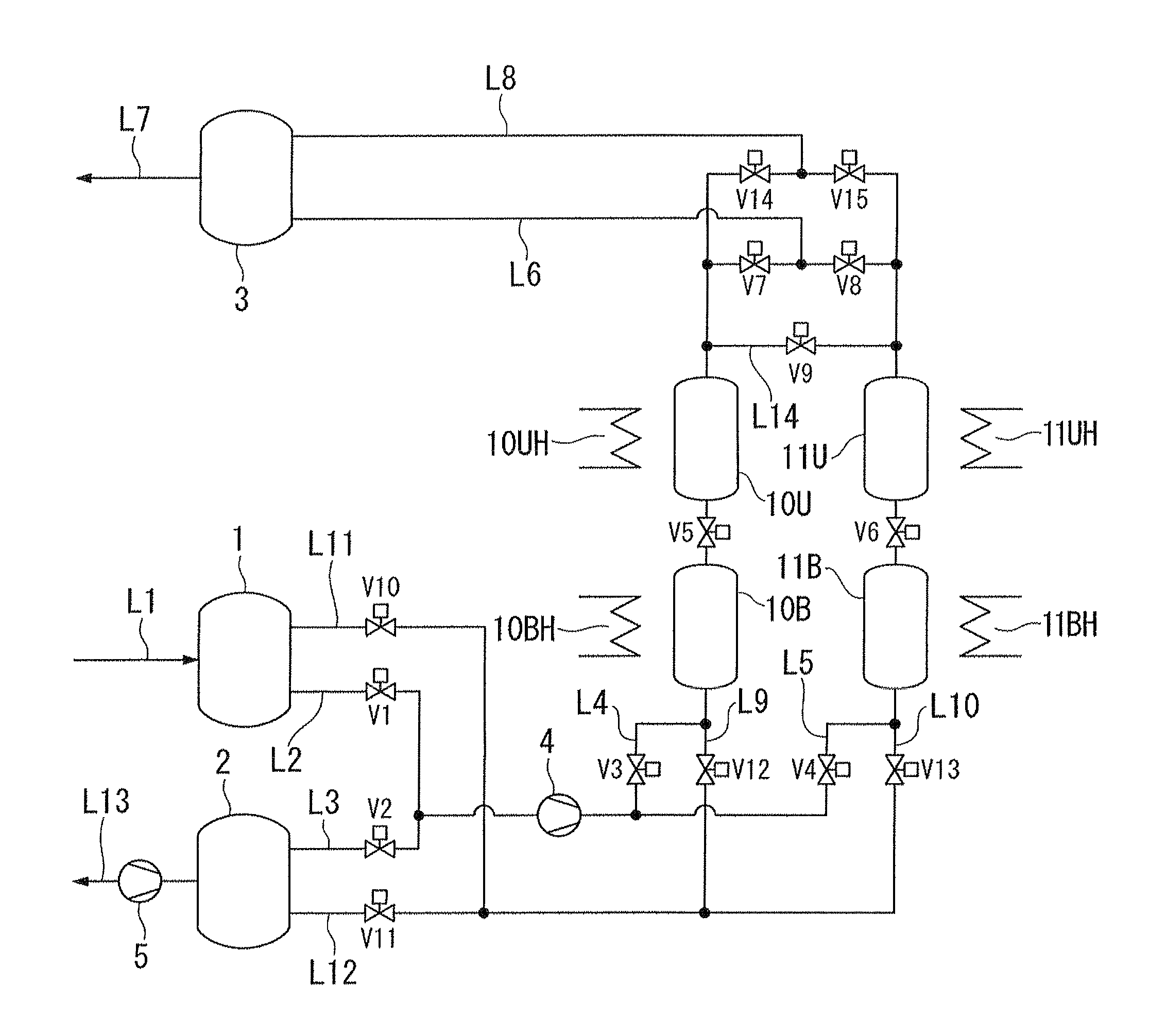
[0117]Similar to Comparative Examples, operations were performed except that heating devices 10BH, 11BH, 10UH and 11 UH, which were not used in Comparative Examples, were used to set a temperature of the columns at 35° C., wherein the position is on the surface of the adsorption columns and corresponds to the middle of a height of an adsorbent-filled layer of each column. Although an ambient temperature was set to 20° C., 25° C. or 30° C., the concentration of xenon included in neon exhausted from a line L7 was about 200 ppm and the concentration of neon included in xenon exhausted from a line L13 was about 40 ppm in any case, that is, uniform results were obtained. The results show that the neon concentration was 99.98%, xenon concentration was about 99.996%, a collection rate of neon was about 99.9996%, and a collection rate of xenon was about 99.8%.

[0118]In this way, it was found that the purity and collection ratio of neon and xenon can be maintained even if an ambient temperatu...


PUM

PropertyMeasurementUnit
temperatureaaaaaaaaaa

Abstract

A method which separates a component which is easily adsorbed by an adsorbent and a component which is not easily adsorbed by the adsorbent, from a feed gas which includes at least two kinds of components, with adsorption columns, wherein the adsorbent is filled in the adsorption columns and has strong adsorbability with respect to at least one kind of component included in the feed gas, and also has weak adsorbability with respect to at least one kind of other components included in the feed gas, and a temperature of the adsorbents which is filled in the column is maintained to be higher than the highest temperature of an ambient temperature around the adsorption columns which is variable throughout the year.

Description

TECHNICAL FIELD[0001]The present invention relates to a pressure swing adsorption-type gas separation method and a pressure swing adsorption-type gas separation apparatus, and more particularly, the present invention relates to a pressure swing adsorption-type gas separation method and a separation apparatus which separate and collect a high value added gas (for example, xenon, krypton and the like) from a gas mixture which includes such a high value added gas.[0002]This application is the U.S. national phase of International Application No. PCT / JP2010 / 001899, filed Mar. 17, 2010, and claims priority on Japanese Patent Application No. 2009-80754, filed Mar. 30, 2009, the contents of each of which are incorporated herein by reference.BACKGROUND ART[0003]In manufacturing steps wherein semiconductor products such as a semiconductor integrated circuit, a liquid crystal panel, a solar battery panel and a magnetic disk are produced, an apparatus has been widely used which generates plasma...

Claims


Application Information

Patent Timeline
Patent Type & Authority Patents(United States)
IPC IPC(8): B01D53/04
CPCB01D2259/40064B01D53/047B01D2257/11C01B23/0052B01D2259/41B01D2259/404B01D2253/102C01B2210/0032B01D53/0438C01B23/0063B01D2256/18C01B2210/0037B01D53/04B01D53/46C01B23/00
Inventor YAMAWAKI, MASAYAISHIHARA, YOSHIOARIMURA, TADANOBU
Owner NIPPON SANSO CORP
Why Eureka
Try Eureka