High rate pulsing wing assembly line

a technology of assembly line and wing, which is applied in the manufacture of tools, metal-working machine components, transportation and packaging, etc., can solve the problems of large-scale, expensive dock assembly system that is not capable of pulsing the wing, and is not practicable for takt time-paced assembly line,

Active Publication Date: 2014-03-04
THE BOEING CO
View PDF5 Cites 79 Cited by
  • Summary
  • Abstract
  • Description
  • Claims
  • Application Information

AI Technical Summary

Problems solved by technology

They use large expensive dock assembly systems that are not capable of pulsing the wing to specialized assembly stations.
The time to move as well as scheduling delays makes this approach impractical for a takt time paced assembly line.
Recurring labor associated with existing production systems can be fairly expensive and requires non-value added time for rotating the wing, setting up the portable drilling equipment and removing, deburring and reinstalling the lower panel.
Additionally, it is not possible to use “C” frame or Yoke automatic fastening systems on closed wing structure such as a wing box with both panels attached.
Manual drilling and fastening which is therefore required may have undesirable ergonomic and quality issues.
These multi-ton large weldments or cast tools which locate the side of body components together are expensive and impractical to move through a horizontal pulsing assembly line.

Method used


Image

  • High rate pulsing wing assembly line
  • High rate pulsing wing assembly line
  • High rate pulsing wing assembly line

Examples


Embodiment Construction

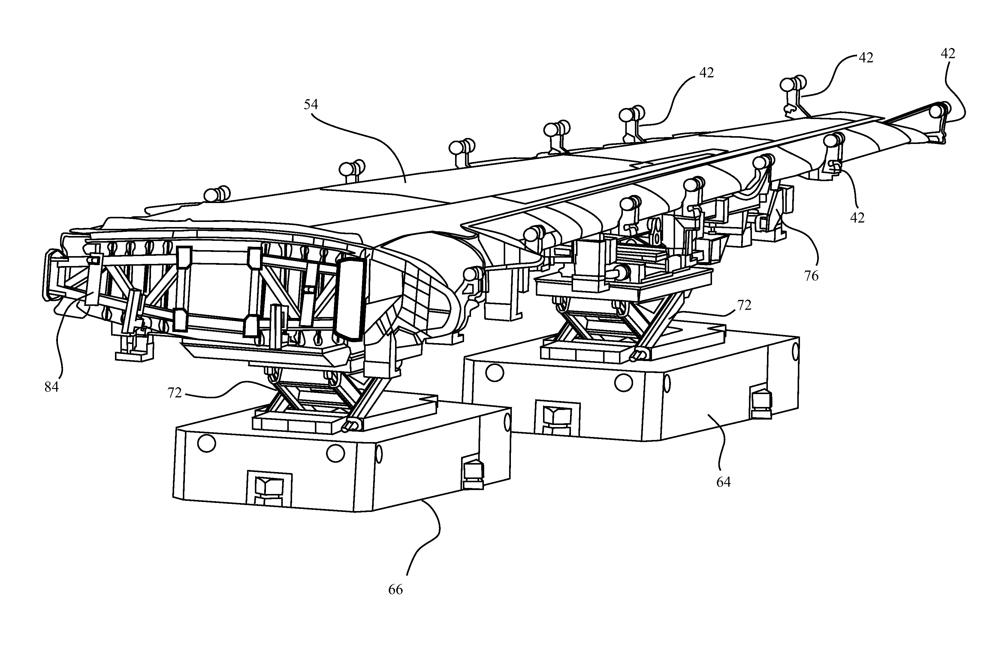
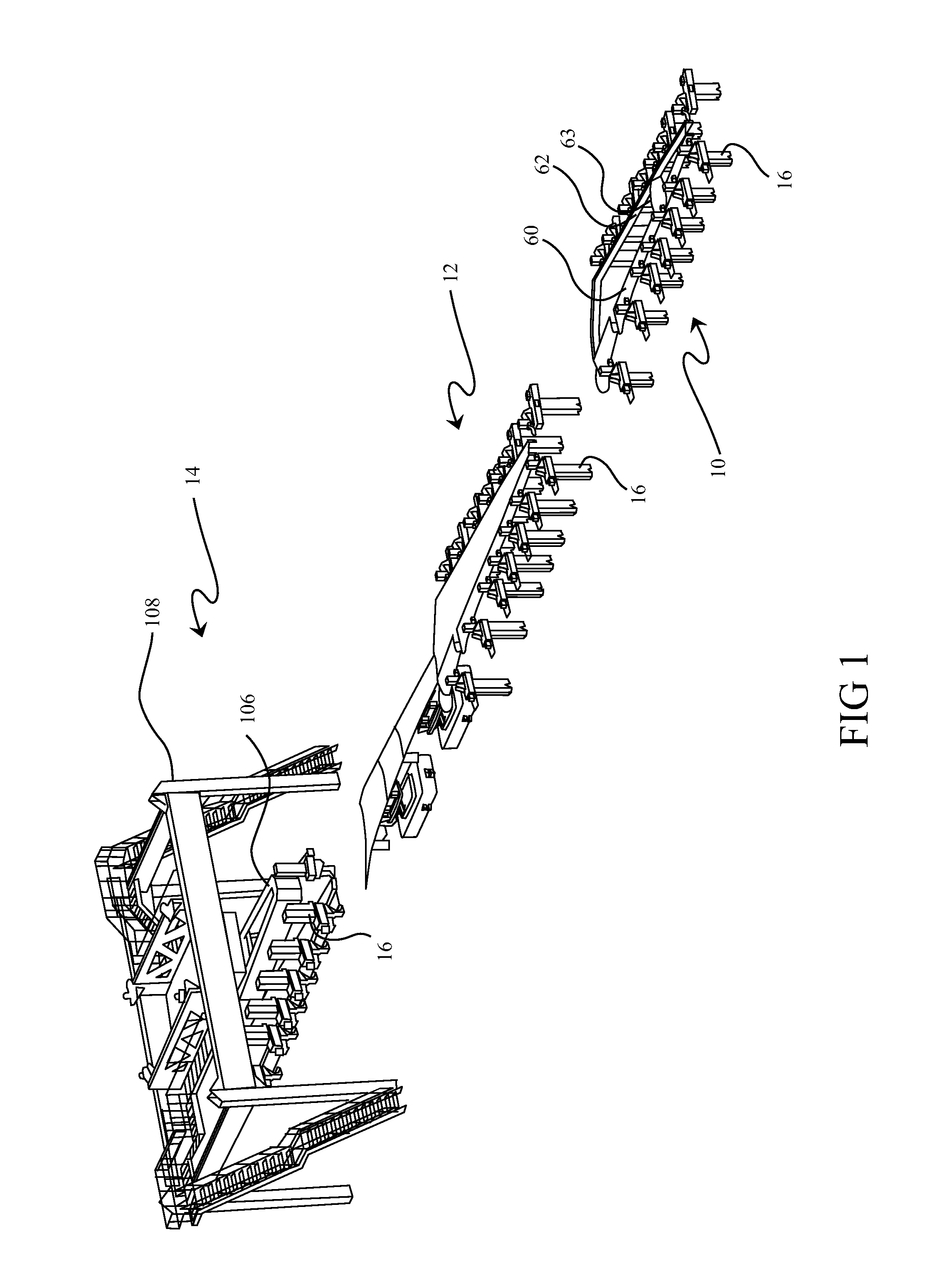
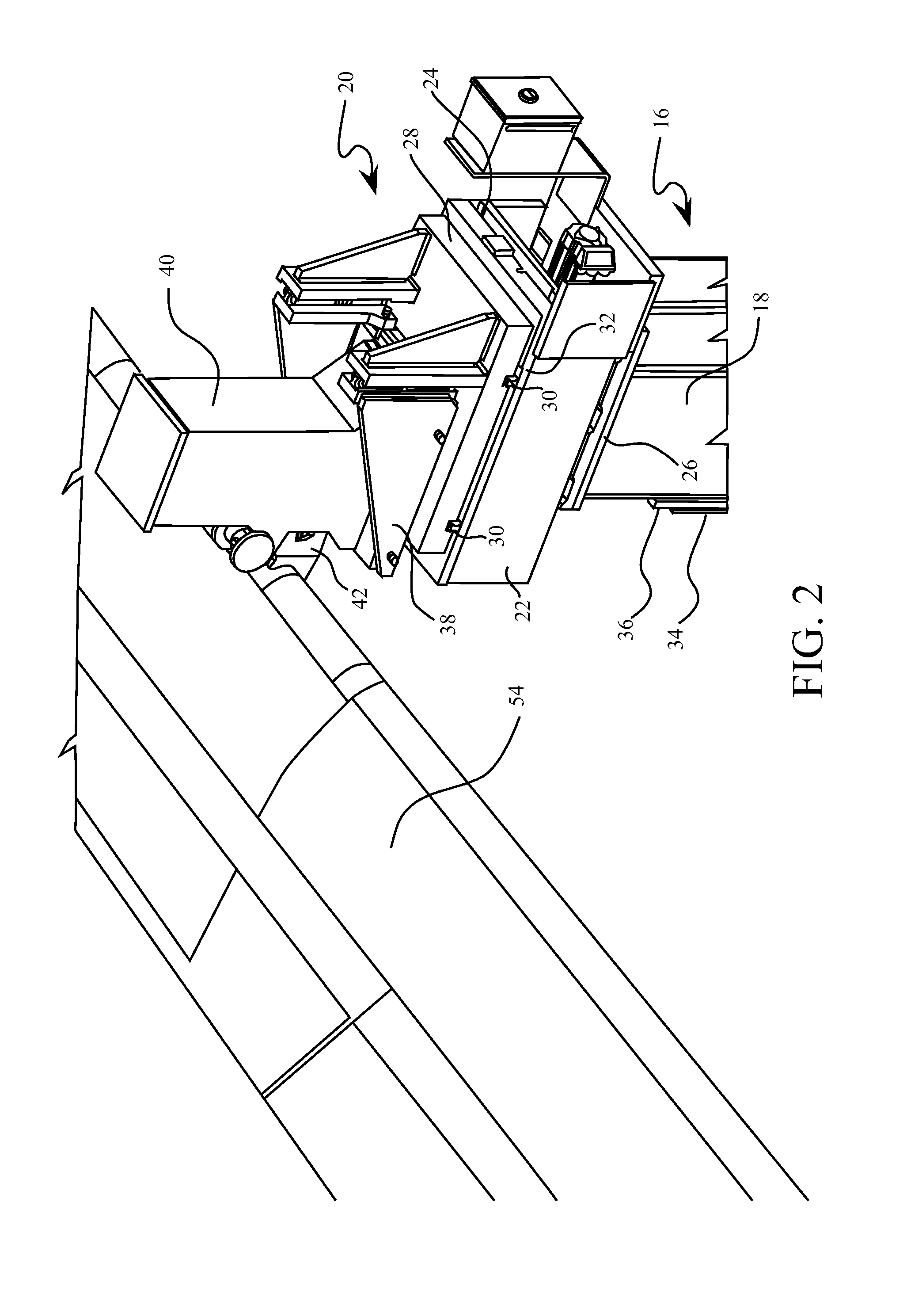
[0036]The embodiments described herein employ determinant assembly (DA) techniques to assemble exemplary main wing components, thereby allowing the assembly fixtures to be smaller and more flexible. The system is a single piece flow, takt time paced pulsing assembly line that moves the wings to positions where mechanics and automated machines perform specialized work. The embodiments described may be mirrored for two linear assembly lines (right and left hand) that have three specialized assembly stations where the mechanics have tools that are optimized to perform efficient location (using determinant assembly features such as surfaces and coordination holes), drilling and fastening operations to the ribs, spars, panels and various structural fittings. The holding fixtures at each position are programmable and retract to provide clearance for the wing moves and to allow compensation for tooling deflection and tooling inaccuracies. A planar locating laser system measures key targets...


PUM

PropertyMeasurementUnit
DAaaaaaaaaaa
DAaaaaaaaaaa
DAaaaaaaaaaa

Abstract

A single piece pulsed flow wing assembly method providing for horizontal wing manufacture is accomplished using synchronized automated vehicles guided in a predetermined manner to move and, locate wing structure in a plurality of assembly positions. Multi-axis assembly positioning systems (MAPS) are used at each assembly position to support and index components in the wing structure and determinant assembly techniques are used for indexing of the components. Modular automated manufacturing processes employing magnetic assembly clamping, drilling, fastener insertion, and sealant application are employed.

Description

REFERENCE TO RELATED APPLICATIONS[0001]This application is copending with application Ser. No. 12 / 550,666 filed on Aug. 31, 2009 entitled AUTONOMOUS CARRIER FOR CONTINUOUSLY MOVING WING ASSEMBLY LINE which is incorporated herein by reference as though fully set forth.BACKGROUND INFORMATION[0002]1. Field[0003]Embodiments of the disclosure relate generally to the field of manufacturing of aircraft subassemblies and more particularly to embodiments for high rate pulsing of an assembly line through multiple positions employing interchangeable automated guide vehicles with task specific headers for transfer to multi-access position systems for subassembly support at each position for determinant assembly.[0004]2. Background[0005]Existing Aircraft wings are assembled in a vertical orientation and are held in large floor mounted assembly fixtures that control the location of the major components until they are fastened together and become sufficiently stable. Wings are then transported wit...

Claims


Application Information

Patent Timeline
Patent Type & Authority Patents(United States)
IPC IPC(8): B21D53/88
CPCB21D53/92B21D53/88B64F5/0009B64F5/10Y10T29/4932Y10T29/49622Y10T29/4978
Inventor BOYD, PHILIP W.HALL, JOHN WMUNK, CLAYTON L.ROBERTS, JAMES C.FANT, MICHAEL J.FIEDLER, RICHARD D.LEWIS, BARRY A.DOBBS, SAMUEL R.MANSELL, GARY E.
Owner THE BOEING CO
Why Eureka
Try Eureka