Flow cell and liquid delivery method

a flow cell and liquid technology, applied in the field of flow cells and liquid delivery methods, can solve the problems of inability to ensure the difficult to provide a sample solution system and a system, and difficulty in ensuring a sufficient level of measurement precision, so as to achieve high level of proficiency, improve workability, and ensure the effect of quality

Active Publication Date: 2014-03-04
NIPPON TELEGRAPH & TELEPHONE CORP
View PDF18 Cites 0 Cited by
  • Summary
  • Abstract
  • Description
  • Claims
  • Application Information

AI Technical Summary

Benefits of technology

[0059]According to the flow cell of the present invention, the liquid delivery timing and the liquid delivery amount of a sample solution can be adjusted in accordance with an operation. Therefore a high level of proficiency is not required for the operator, and measurements can be performed simply at a high level of precision so that workability is improved.
[0060]Moreover, according to the liquid delivery method for a flow cell of the present invention, the liquid delivery timing and the liquid delivery amount of the sample solution, and the liquid delivery timing and the liquid delivery amount of the reference solution can be adjusted in accordance with the operation. Therefore, the sample solution and the reference solution do not get mixed in the inlet section, and no air gap is formed between the sample solution and the reference solution flowing through the flow channel, so that the respective solutions can be delivered to the flow channel simply, giving a superior workability and improving the level of measurement precision.
[0061]Furthermore, according to the flow cell and the liquid delivery method of the present invention, there is provided the reserve section for accumulating a reference solution in the inlet section. Therefore the operator does not have to supply the reference solution to the inlet section every time when performing measurements, and the accumulated reference solution can be delivered to the detecting section of the flow channel by just unsealing the reserve section. Consequently the level of measurement workability can be increased with a simple configuration. Moreover, a predetermined amount of the reference solution preliminarily accumulated in the inlet section is delivered by unsealing the reserve section. Therefore the operator can actively control the liquid delivery timing and the liquid delivery amount, thereby increasing the level of measurement precision.

Problems solved by technology

In a case of performing this type of measurement with a flow cell, it is not easy to provide a system of the sample solution and a system of the reference solution on the same cell.
Here, in a state where the solution is sufficiently accumulated in the inlet section, if the next different solution is supplied, these solutions are mixed with each other, making it difficult to ensure a sufficient level of measurement precision.
Accordingly, it becomes difficult to make a comparison in the trace amount of variation between the measurement result of the reference solution and the measurement result of the sample solution, so that the level of measurement precision cannot be ensured.
Therefore, in a case where a single operator is operating the plurality of measurement devices, the burden on the operator is significant.
Furthermore, since the operation is complex, a series of measurements, in which a plurality of sample solutions are continuously measured, cannot be performed quickly and measurement intervals become long, so that workability is obstructed.
However, in this case, the structure of the flow cell becomes complex.
However, when respectively supplying the reference solution and the sample solution to the flow cell, if syringe pumps, the liquid switch, the tube, and the like are used as described above, there is a problem in that the configuration of the device becomes complex and consequently the cost of equipment increases.
Moreover, in order to ensure the level of measurement precision, there are laborious tasks which need to be performed for each sample solution measurement, such as replacing, cleaning, and drying these syringe pumps, the liquid switch, the tube and the like, and this obstructs measurement workability.
Here, if the sample solution is supplied in a state where the reference solution is sufficiently accumulated in the inlet section, these solutions are mixed with each other, making it difficult to ensure the level of measurement precision.
As a result, it becomes difficult to make a comparison in the trace amount of variation between the measurement result of the reference solution and the measurement result of the sample solution, so that the level of measurement precision cannot be ensured.
Therefore the operation becomes complex and this creates a burden on the operator.
Furthermore, since the operation is complex, a series of measurements, in which a plurality of sample solutions are continuously measured, cannot be performed quickly and measurement intervals become long, so that workability is obstructed.
However, in this type of method, since a detecting section facing the flow channel is exposed to the reference solution for a prolonged period of time, the detecting section becomes deteriorated and this influences the measurement precision.

Method used


Image

  • Flow cell and liquid delivery method
  • Flow cell and liquid delivery method
  • Flow cell and liquid delivery method

Examples


first embodiment

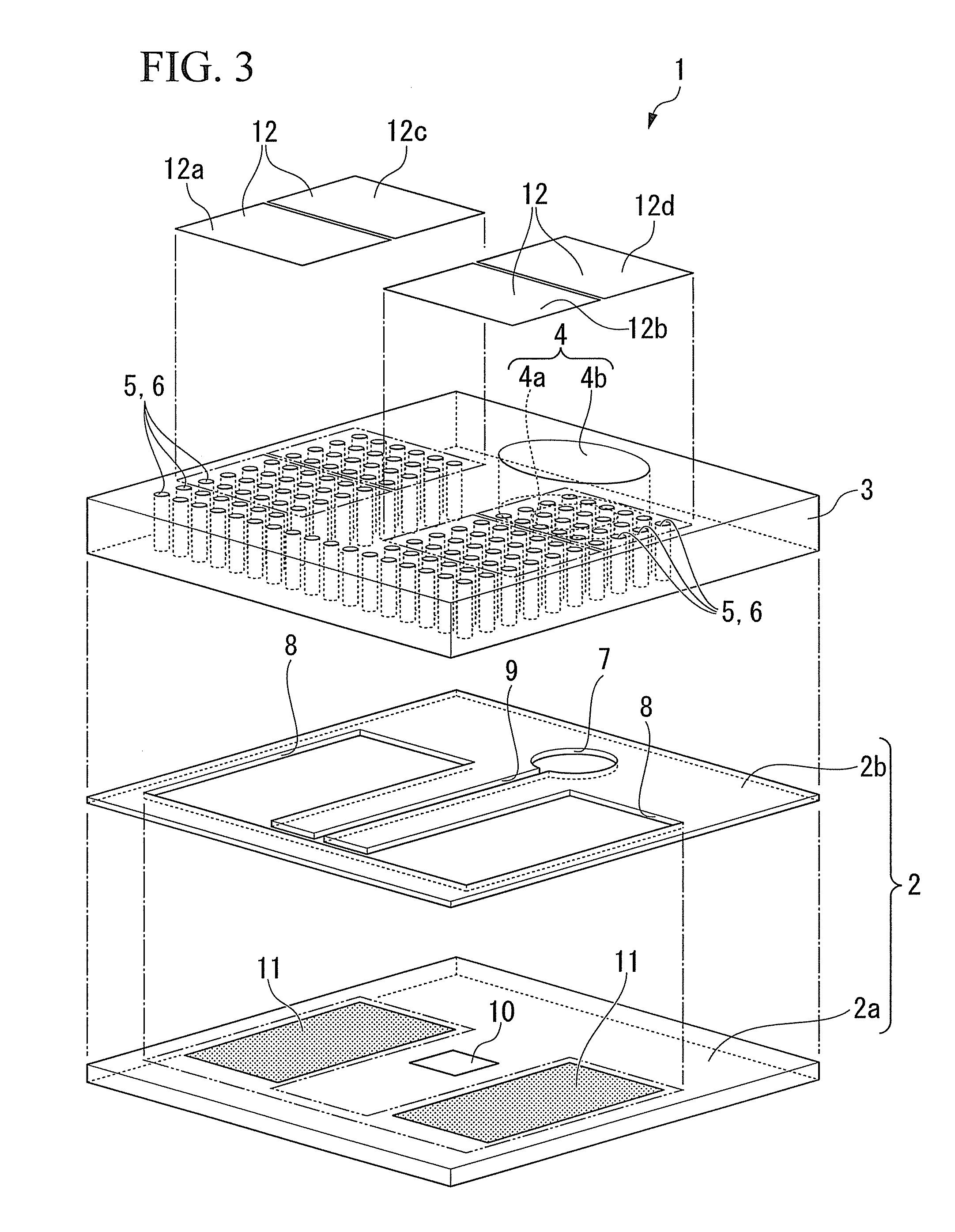
[0121]As described above, according to the flow cell 1 of the first embodiment, the opening sections 6 of the through holes 5, which draw in and guide the respective solutions of the sample solution, the reference solution, and the PBS liquid, are sealed by the sealing members 12. Therefore, in the state where the respective solutions are accumulated in the solution supply hole 4, the respective solutions do not flow into the flow channel 9 until the sealing members 12 have opened the opening sections 6. Moreover, the respective sealing members 12a to 12d seal the respective opening sections 6, and it is consequently possible to decide the liquid delivery amount of the respective solutions according to the range where these sealing members 12a to 12d are detached to open the opening sections 6.

[0122]That is to say, the respective solutions are only transferred to the through holes 5 corresponding to the respective opening sections 6 opened by the respective sealing members 12a to 12...

second embodiment

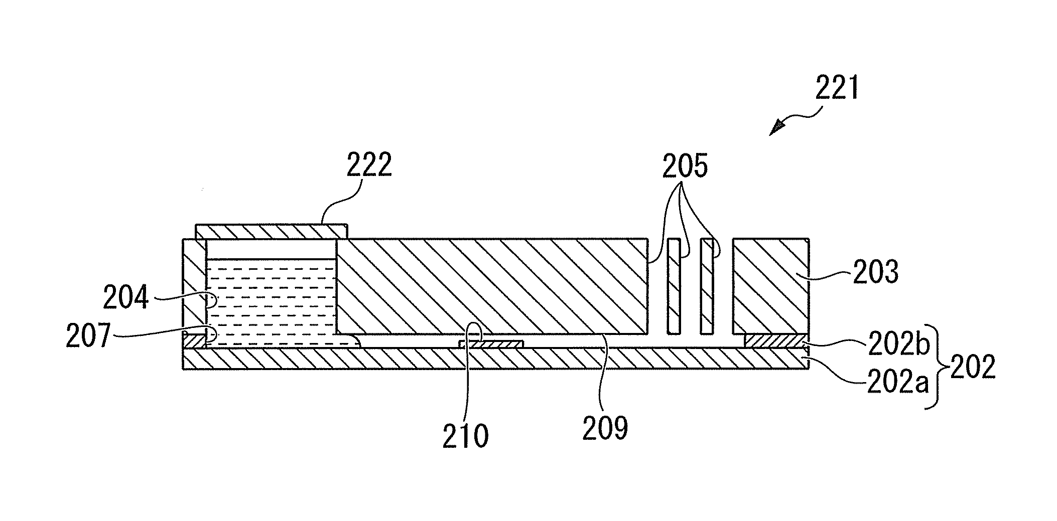
[0128]Next, the present invention is described, with reference to FIG. 5 to FIG. 8.

[0129]FIG. 5 is an exploded perspective view showing a schematic configuration of a flow cell according to the second embodiment of the present invention. FIG. 6 is a plan view showing the schematic configuration of the flow cell according to the second embodiment of the present invention. FIG. 7 is a sectional side view taken along the line A1-A1 in FIG. 6. FIG. 8 is a sectional side view taken along the line B1-B1 in FIG. 6.

[0130]Members the same as those in the first embodiment described above are denoted by the same reference symbols, and descriptions thereof are omitted.

[0131]An upper substrate 23 of a flow cell 21 of the second embodiment, on one end side of the substantially center (on the upper-right side in FIG. 5, or on the top side in FIG. 6) in the widthwise direction in a plan view thereof (in the upper-left to lower-right direction in FIG. 5, or in the left-right direction in FIG. 6), is...

third embodiment

[0156]Next, the present invention is described, with reference to FIG. 9 and FIG. 10.

[0157]FIG. 9 is a plan view showing a schematic configuration of a flow cell according to the third embodiment of the present invention. FIG. 10 is a sectional side view taken along the line C1-C1 in FIG. 9.

[0158]Members the same as those in the first and second embodiments described above are denoted by the same reference symbols, and descriptions thereof are omitted.

[0159]An upper substrate 43 of a flow cell 41 of the third embodiment is formed with a polymer material or the like. On one side (on the left side in FIG. 9) and on the other side (on the right side in FIG. 9) in the widthwise direction in a plan view of the flow cell 41 (the left-right direction in FIG. 9), there are respectively provided a plurality of rectangular recess groove-shaped chambers (transfer section) 45 which open toward the lower surface side in the plate thickness direction. These chambers 45 are formed so as to extend ...


PUM

PropertyMeasurementUnit
plate thicknessaaaaaaaaaa
thicknessaaaaaaaaaa
heightaaaaaaaaaa

Abstract

A flow cell includes: a flow channel through which a sample solution flows; an inlet section which communicates with the flow channel and to which the sample solution is supplied; a transfer section which includes a plurality of opening sections, one end side of which communicates with the flow channel and an other side of which opens to outside air, and which communicates with the flow channel, and draws in and guides the sample solution supplied into the inlet section to the flow channel; a detecting section which faces the sample solution in the flow channel; and a sealing member which unsealably seals at least either one of the opening section or the inlet section.

Description

TECHNICAL FIELD[0001]The present invention relates to a flow cell and a liquid delivery method. Priority is claimed on Japanese Patent Application No. 2008-141463, filed May 29, 2008, and Japanese Patent Application No. 2008-141464, filed May 29, 2008, the contents of which are incorporated herein by reference.BACKGROUND ART[0002]Measurement which uses a function for identifying highly advanced biologic molecules such as an antigen-antibody reaction and a bond between a DNA fragment (DNA probe) and a DNA, is an important technique in measurement in the areas of clinical testing and biochemistry and in environmental pollutant measurement. Examples of this type of measurement include micro TAS (Total Analysis Systems), micro combinatorial chemistry, chemical IC, chemical sensors, biosensors, microanalysis, electrochemical analysis, QCM measurement, SPR measurement, and ATR measurement. In the area of these types of measurement, the amount of a measurement target sample solution is ver...

Claims


Application Information

Patent Timeline
Patent Type & Authority Patents(United States)
IPC IPC(8): G01N33/00
CPCB01L2200/0621G01N2035/1039B01L2400/0694B01L3/50273B01L2300/0864B01L3/502723B01L2200/16B01L2300/0829B01L2400/0406G01N21/553G01N2021/0346B01L3/5025B01L2200/148B01L3/502715G01N21/05Y10T436/25
Inventor HORIUCHI, TSUTOMUMIURA, TORUIWASAKI, YUZURUSEYAMA, MICHIKOHAYASHI, TSUYOSHITAKAHASHI, JUN-ICHIHAGA, TSUNEYUKI
Owner NIPPON TELEGRAPH & TELEPHONE CORP
Why Eureka
Try Eureka