Pseudo-apposition eye spectral imaging system

a spectral imaging and pseudo-apposition technology, applied in the field of spectral imaging systems, can solve the problems of insufficient miniaturized camera systems, bulky systems, and high cost, and achieve the effect of increasing the angle of inciden

Active Publication Date: 2014-03-04
MERCURY MISSION SYST LLC
View PDF5 Cites 86 Cited by
  • Summary
  • Abstract
  • Description
  • Claims
  • Application Information

AI Technical Summary

Benefits of technology

[0003]According to various embodiments of the invention, a multi-spectral imaging system is presented. The system comprises an array of parallel spectral channels, each channel is an independent imaging system, with a microlens and a spectral filter. Imaging multiplicity arising from the array of microlenses is used to provide

Problems solved by technology

These systems are inadequate for miniaturized camera systems because of their size, weight, and cost.
Commercial multispectral camera systems frequently use tunable filters and monochrome sensors with various lens options (15 to 100 mm

Method used


Image

  • Pseudo-apposition eye spectral imaging system
  • Pseudo-apposition eye spectral imaging system
  • Pseudo-apposition eye spectral imaging system

Examples


first embodiment

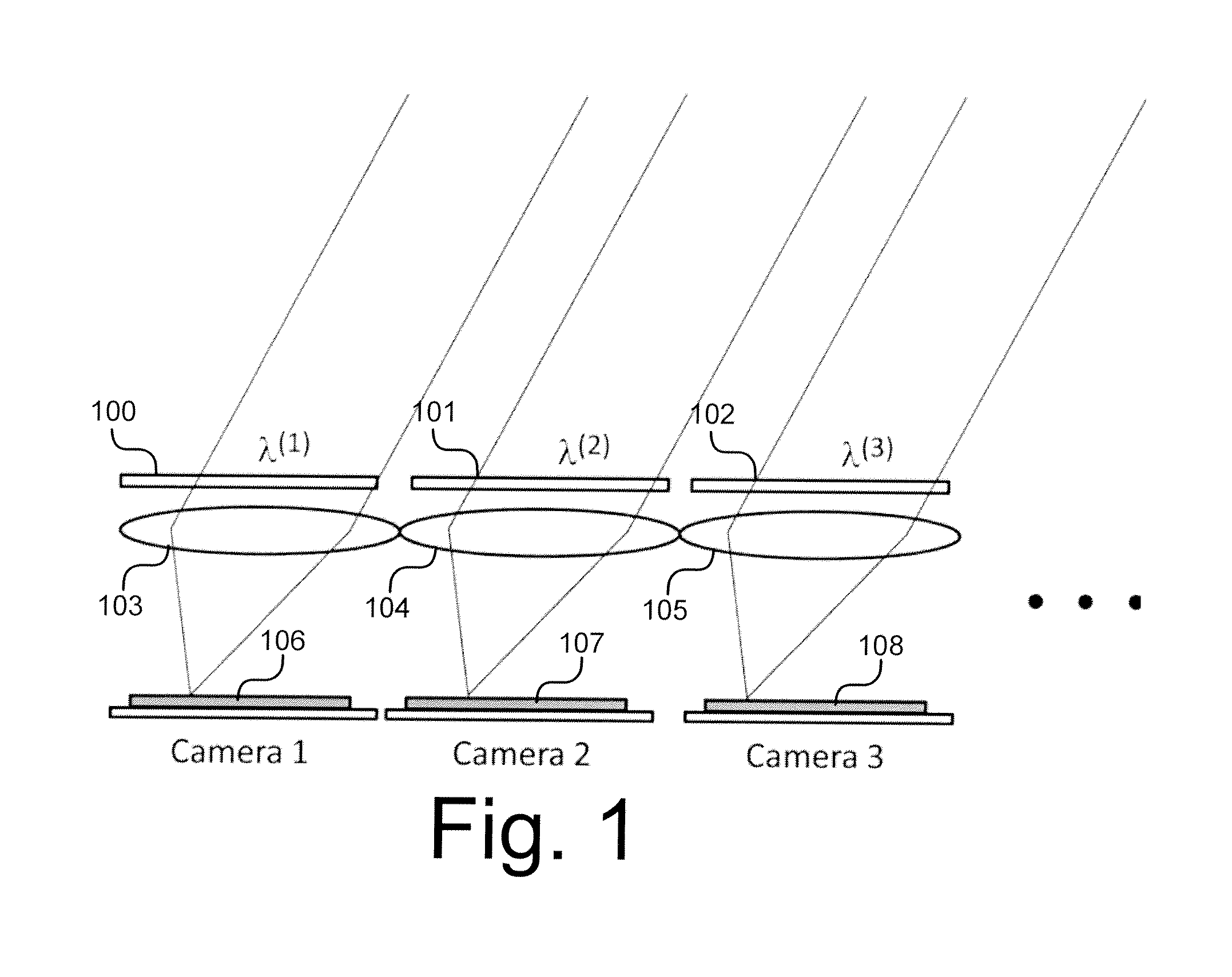
[0008]FIG. 1 illustrates the invention.

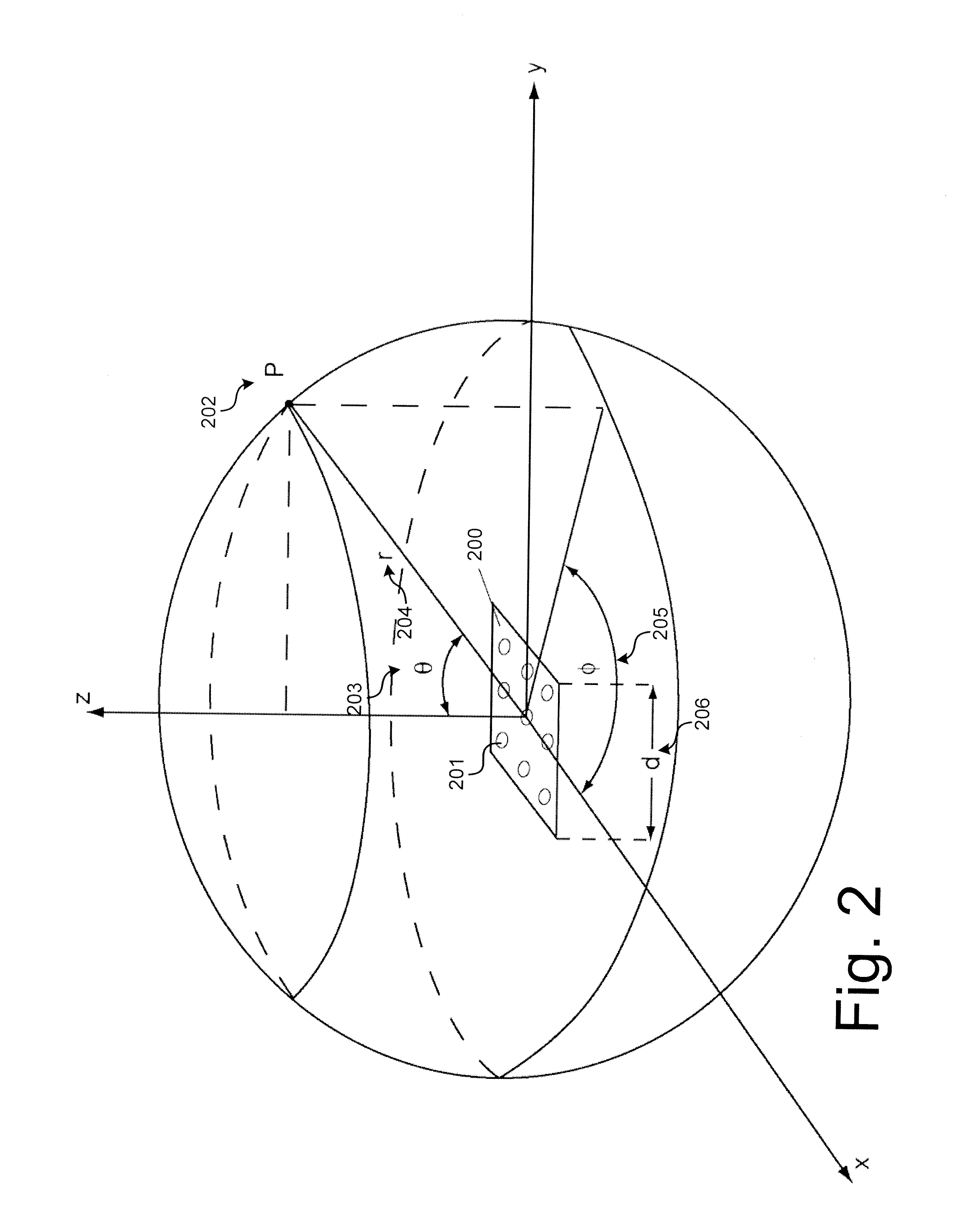
[0009]FIG. 2 illustrates variables and system parameters for assistance in describing various aspects of embodiments of the invention.

second embodiment

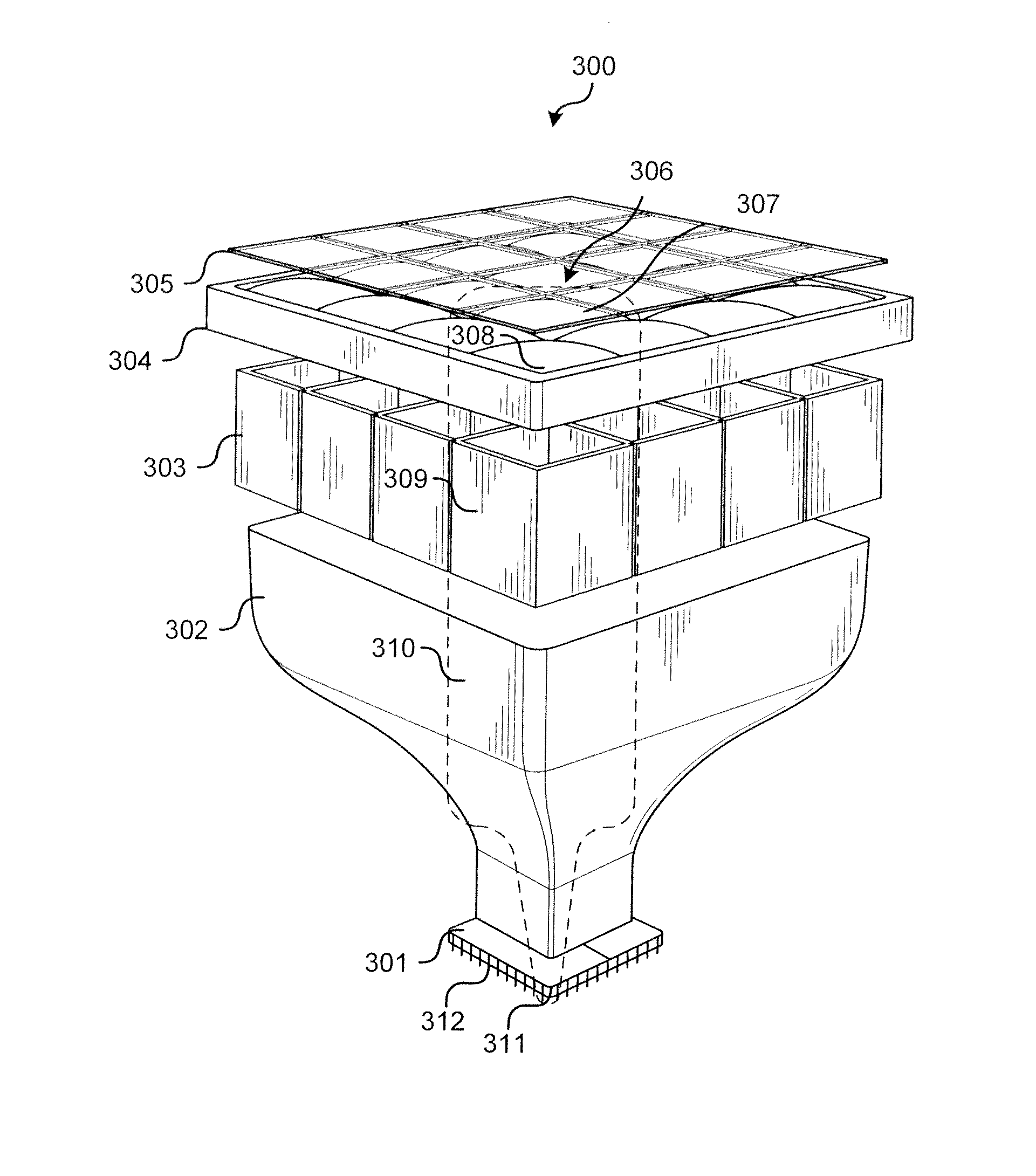
[0010]FIG. 3 illustrates the invention, illustrated in an exploded view.

[0011]FIG. 4 illustrates a spectral unit implemented in accordance with an embodiment of the invention.

[0012]FIG. 5 graphs the wavelength / angular dependence for incident light of three wavelengths and for a lens with refractive index n=1.55.

[0013]FIG. 6 illustrates a filter binarization process implemented in accordance with an embodiment of the invention.

[0014]Filter 7 illustrates a graph of a spectro-angular map implemented in accordance with an embodiment of the invention.

[0015]FIG. 8 illustrates a comparison between the geometric loci of focal points of a filter and lens combination and a lens alone.

[0016]FIG. 9 illustrates a spectral signature identification process in a hyperspectral imaging system implemented in accordance with an embodiment of the invention.

[0017]FIG. 10 illustrates a method of system operation implemented in accordance with an embodiment of the invention.

[0018]FIG. 11 illustrates a spec...

embodiment 300

[0033]In some embodiments, the image sensor 301 may comprise an sCMOS sensor array sensitive from (200-1,000 nm), and in further embodiments may include SWIR (1,000-1,700 nm) or MWIR+LWIR (3-14 micron) sensor arrays. A processing module 312, such as an FPGA or DSP image processor, may be coupled to the image sensor 301. In the illustrated embodiment 300, the arrays of filters 305, microlenses 304, and microchannels 303 are planar arrays, such as N×M grids (a 4×4 grid is shown). In other embodiments, the arrays may be spherical, semispherical, linear, or in some other configuration, and various numbers of elements may make up the arrays. In particular embodiments, the lens array 304 may comprise a microlens array with pitch ranges from 100 to 1,000 microns, focal lengths between 0.5 and 5 mm, and lens diameters from 150 to 1,000 μm.

[0034]The illustrated arrays 305, 304, and 303 provide the system 300 with a plurality of physical channels or spectral units 306. Each spectral unit 306 ...


PUM


Abstract

A spectral imaging system comprises a plurality of spectral units arranged in an array, each spectral unit of the plurality of spectral units comprising: a microlens having an optical axis; a spectral filter having a center wavelength and aligned with the optical axis; a fiber optic bundle, the fiber optic bundle having a curved light receiving surface and a planar light output surface, wherein the curved light receiving surface is aligned with the optical axis; and a plurality of pixel sensors configured to receive light from the planar light output surface of the fiber optic taper portion.

Description

TECHNICAL FIELD[0001]The present invention relates generally to imaging systems, and more particularly, some embodiments relate to spectral imaging systems.DESCRIPTION OF THE RELATED ART[0002]Currently available spectral imaging systems typically use methods such as color wheels, prisms, and liquid-crystal tunable filters. These systems are inadequate for miniaturized camera systems because of their size, weight, and cost. Commercial multispectral camera systems frequently use tunable filters and monochrome sensors with various lens options (15 to 100 mm focal length) that make their physical size prohibitive for military, medical, or machine vision applications. In addition to making these systems bulky and expensive, these difficulties have prevented development of handheld versions.BRIEF SUMMARY OF EMBODIMENTS OF THE INVENTION[0003]According to various embodiments of the invention, a multi-spectral imaging system is presented. The system comprises an array of parallel spectral ch...

Claims


Application Information

Patent Timeline
IPC IPC(8): G01N21/25G01J3/46
CPCG01J3/0205G01J3/0208G01N21/25G01N2021/317G01J2003/2806G01J3/46G01J2003/1213G01J3/0218G01J3/28G01N21/31
Inventor KOMPANIETS, IOURI V.JANNSON, TOMASZPRADHAN, RANJIT
Owner MERCURY MISSION SYST LLC
Why Eureka
Try Eureka