Eccentric gear arrangement

a gear arrangement and eccentric technology, applied in the direction of power driven reciprocating saws, metal sawing devices, manufacturing tools, etc., can solve the problems of increased service life caused by wear, increased power, and developed temperature, so as to improve the eccentric drive arrangement, reduce friction losses, and increase the operating reliability

Active Publication Date: 2014-03-11
ANDREAS STIHL AG & CO KG
View PDF8 Cites 8 Cited by
  • Summary
  • Abstract
  • Description
  • Claims
  • Application Information

AI Technical Summary

Benefits of technology

[0006]It is an object of the invention to improve an eccentric drive arrangement of the kind described above such that an increased operating reliability is provided with reduced friction losses.
[0009]With the arrangement according to the invention, a holding force can be applied to the two contact pressure surfaces, independently of each other and directly, without it being necessary to transfer this holding force through the outer shearing blade and to the inner shearing blade. Accordingly, no additional friction caused by the holding force occurs between the two shearing blades. Friction and wear are reduced. Also, the temperature developed because of friction is limited, so that the lubricant fill of the eccentric gear arrangement can unfold without impairing its lubricating effect. The drive power, which is required at high loads, is reduced, while the service life caused by wear is increased.
[0010]It can be practical to arrange the contact pressure surfaces, for example, laterally of the connecting links. In this case, the contact pressure surface of the first shearing blade lies, for example, on the left-hand side and the contact pressure surface of the second shearing blade lies on the opposite right-hand side. Thus, the two contact pressure surfaces are prevented from covering each other, so that a contact pressure force can be applied directly onto the contact pressure surfaces by means of the downholder. In an advantageous embodiment, the shearing blades have respective contact pressure extensions running parallel to the displacement path. The contact pressure extensions are arranged on a rear end of the shearing blades lying opposite to the shearing sections in the direction of the displacement path and are offset laterally with respect to each other in a lateral direction lying transversely to the displacement path. The contact pressure surfaces are formed on the contact pressure extensions. A mutual covering is avoided independently of the displacement path because of the lateral offset of the two contact pressure extensions. The contact pressure extensions are arranged on the rear end and extend in the longitudinal direction of the shearing blades, that is, in the direction of the displacement path. For this reason, little installation space is needed in the lateral direction, whereby the arrangement can be kept slim and compact. Lateral eccentricities in the introduction of force are minimized.
[0011]In an advantageous further embodiment, the contact pressure extensions with their contact pressure surfaces are of a length which is at least approximately equal to the displacement path. This ensures that the downholders at least approximately can act on the assigned contact pressure surfaces over the entire displacement path. Accordingly, the down-holding effect is maintained at least approximately over the entire displacement path.
[0013]A gear housing is provided for accommodating the eccentric wheel as well as the shearing blades in the region of their connecting links and their contact pressure surfaces. Here, it can be practical to configure the downholders directly on the gear housing, that is, on the housing cover thereof. However, it is advantageous to arrange, in the gear housing, a holding plate including the downholders. Especially at least one and preferably the two further downholders are arranged on the holding plate, with the downholders acting on the lateral contact pressure surfaces. In this way, the housing is relieved of load, so that it can be manufactured of thin-walled and lightweight light-metal casting or the like. The holding plate can, for example, be manufactured of steel plate or any other high-strength material for accommodating the high holding forces, regardless of the selected material of the gear housing.
[0015]In a preferred embodiment, the holder plate is held between the housing shell and the housing cover of the gear housing especially via threaded fasteners and / or via clamping and / or via form-locking. After removal of the housing cover, the holding plate can be removed easily, for example, to be able to exchange the shearing blades. Furthermore, the attachment of the holding plate between the housing shell and the housing cover leads to a favorable and large surface distribution of force introduction which favors the objective of a lightweight construction.

Problems solved by technology

Also, the temperature developed because of friction is limited, so that the lubricant fill of the eccentric gear arrangement can unfold without impairing its lubricating effect.
The drive power, which is required at high loads, is reduced, while the service life caused by wear is increased.

Method used


Image

  • Eccentric gear arrangement
  • Eccentric gear arrangement
  • Eccentric gear arrangement

Examples


Embodiment Construction

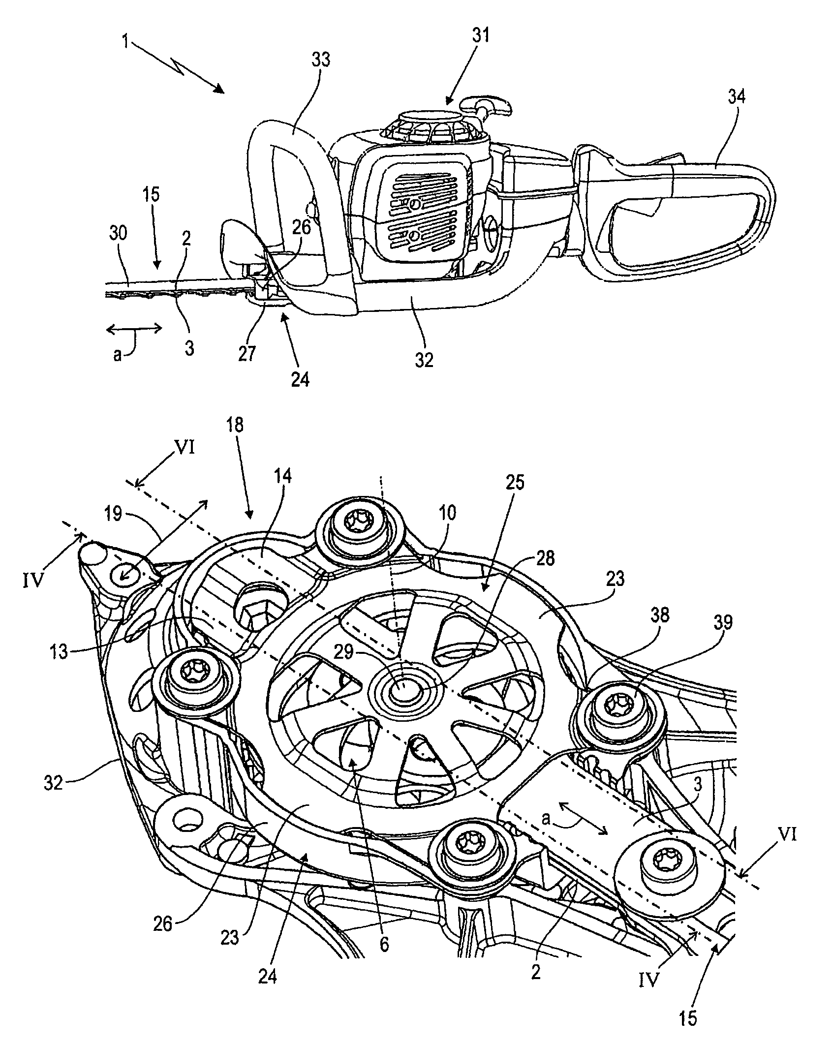
[0024]FIG. 1 shows, in a perspective view, a hand-guided hedge trimmer 1 having a drive motor 31 not shown in greater detail as well as a housing 32, a front handle 33 and a rear handle 34. The drive motor can be an electric motor operated from power mains or operated from batteries and, in the embodiment, the drive motor is a single-cylinder, two-stroke combustion engine. The engine could also be a four-stroke combustion engine.

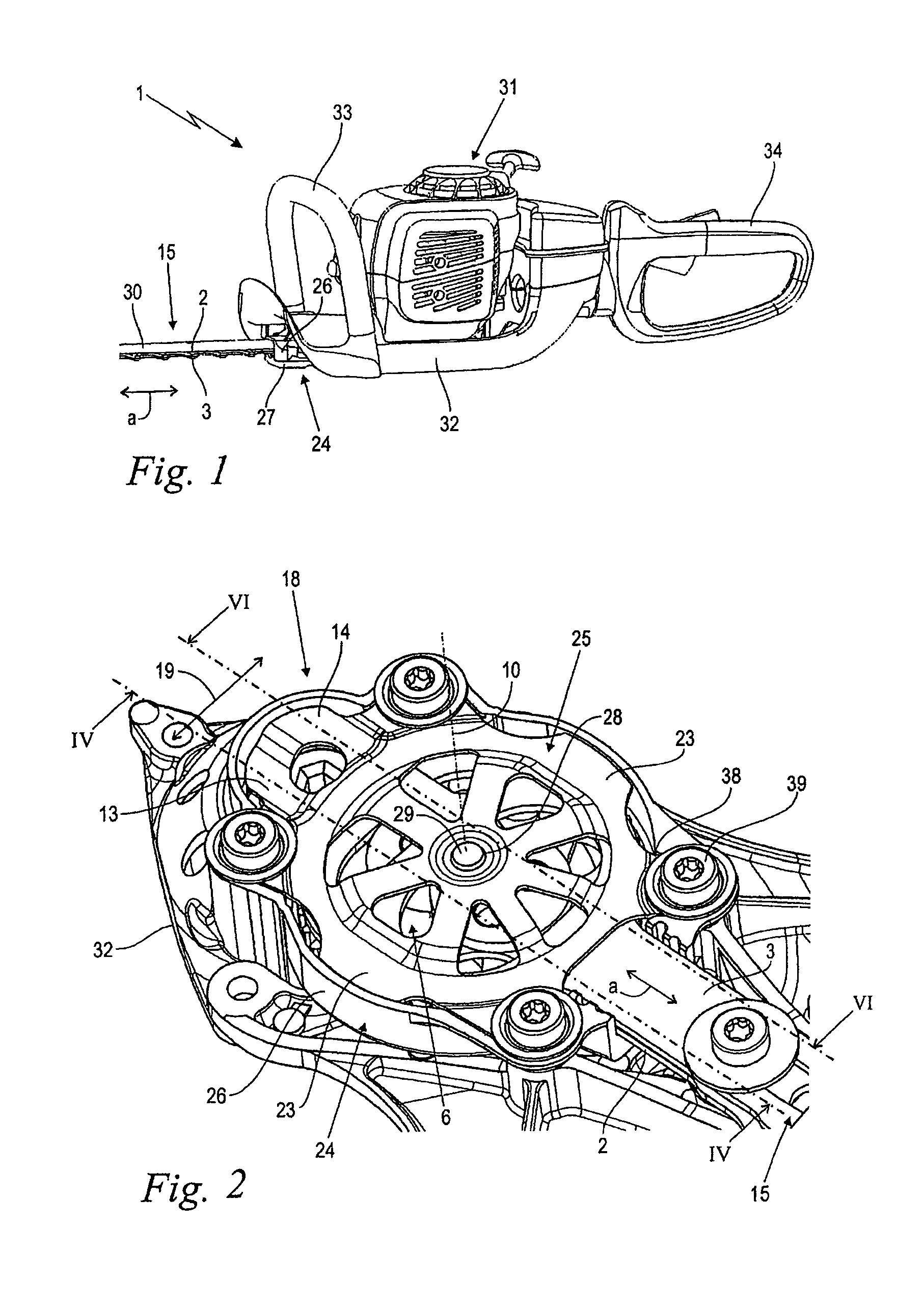
[0025]An eccentric gear arrangement according to the invention is arranged on the front end of the housing 32 facing away from the user. The eccentric gear arrangement includes two shearing blades (2, 3), which are driven in opposite directions over a displacement path (a), as well as a gear housing 24 having a housing shell 26 and a removable housing cover 27. The housing shell 26 can be formed or attached to the housing 32. The two shearing blades (2, 3) lie with their motor-near section in the gear housing 24 and have a shearing section 15 with shearing t...


PUM

PropertyMeasurementUnit
contact pressureaaaaaaaaaa
lengthaaaaaaaaaa
shearing forcesaaaaaaaaaa

Abstract

The invention relates to an eccentric gear arrangement of a motor-driven, hand-guided hedge trimmer (1). The eccentric gear arrangement includes two shearing blades (2, 3) driven in mutually opposite directions over a displacement path (a). Each shearing blade has a connecting link (4, 5) as well as an eccentric wheel (6) having a drive wheel (7) and two eccentrics (8, 9). The eccentric wheel (6) rotates about a rotational axis (10). The two connecting links (4, 5) lie directly above one another. The two eccentrics (8, 9) are arranged on the same side of the drive wheel (7) and engage each in one of the two connecting links (4, 5). The two shearing blades (2, 3) have contact pressure surfaces (11, 12) in the region of their two connecting links (4, 5) and are offset with respect to each other in such a manner that they are exposed at least over a portion of the displacement path (a). Two downholders (13, 14) are provided which act each on one of the assigned contact pressure surfaces (11, 12).

Description

CROSS REFERENCE TO RELATED APPLICATION[0001]This application claims priority of German patent application no. 10 2010 005 964.1, filed Jan. 28, 2010, the entire content of which is incorporated herein by reference.BACKGROUND OF THE INVENTION[0002]Motor-driven, hand-guided hedge cutters include two shearing blades running in mutually opposite directions. In such hedge cutters, eccentric drives are used in addition to connecting rod drives, wherein a rotatingly driven eccentric wheel is provided which has two eccentrics mutually offset by 180°. These two eccentrics engage in connecting links of the two shearing blades whereby the shearing blades are oscillatingly driven in mutually opposite directions.[0003]In a known configuration, the two shearing blades including their two connecting links lie directly one atop the other. The two eccentrics are arranged on the same side of the corresponding drive wheel and engage in one of the two connecting links. This facilitates the exchange of ...

Claims


Application Information

Patent Timeline
Patent Type & Authority Patents(United States)
IPC IPC(8): B23D49/00
CPCA01G3/053
Inventor HITTMANN, MARKUSSCHENK, RALFFRIEDRICH, REINHARDMAYER, GUNTER
Owner ANDREAS STIHL AG & CO KG
Why Eureka
Try Eureka